- Overview
- Configuration modes
- General settings
- Connection settings
- Data mapping
- Requests mapping
- Advanced configuration
- Additional information
- Next steps
Overview
This documentation will help you set up the OPC-UA connector for the ThingsBoard IoT Gateway. We’ll explain the configuration parameters in simple terms to make it easy for you to understand and follow. The OPC-UA (Open Platform Communications Unified Architecture) is a machine-to-machine communication protocol for industrial automation, and this connector allows seamless integration with the ThingsBoard platform. Use general configuration to enable this connector.
Also, if you are new to ThingsBoard IoT Gateway, we recommend you to read the Getting Started guide to understand the basic concepts of ThingsBoard IoT Gateway and how it works with OPC-UA protocol.
The connector can be configured via the user interface form, which helps you set up a connection to the OPC-UA server, collect data and write data to nodes. Let’s look at all the available settings and explain each one clearly. This will help you understand how everything works.
Please note: To access the actual UI for the gateway - you need to a have connected gateway before adding a connector. Otherwise, you will see the old UI.
Configuration modes
The OPC-UA connector can be configured in two modes: Basic and Advanced.
- Basic mode is designed for users who are new to ThingsBoard IoT Gateway and want to quickly set up the connector with minimal configuration. It provides a simplified interface with essential settings.
- Advanced mode is intended for experienced users who need more control over the configuration. It offers additional options and flexibility for advanced use cases.
Please note: If you are new to IoT Gateway, use the “Basic” configuration mode. If you are familiar with configuring IoT Gateway, you can use the “Advanced” configuration mode.
You can switch between these modes using the toggle button at the top of the configuration page:
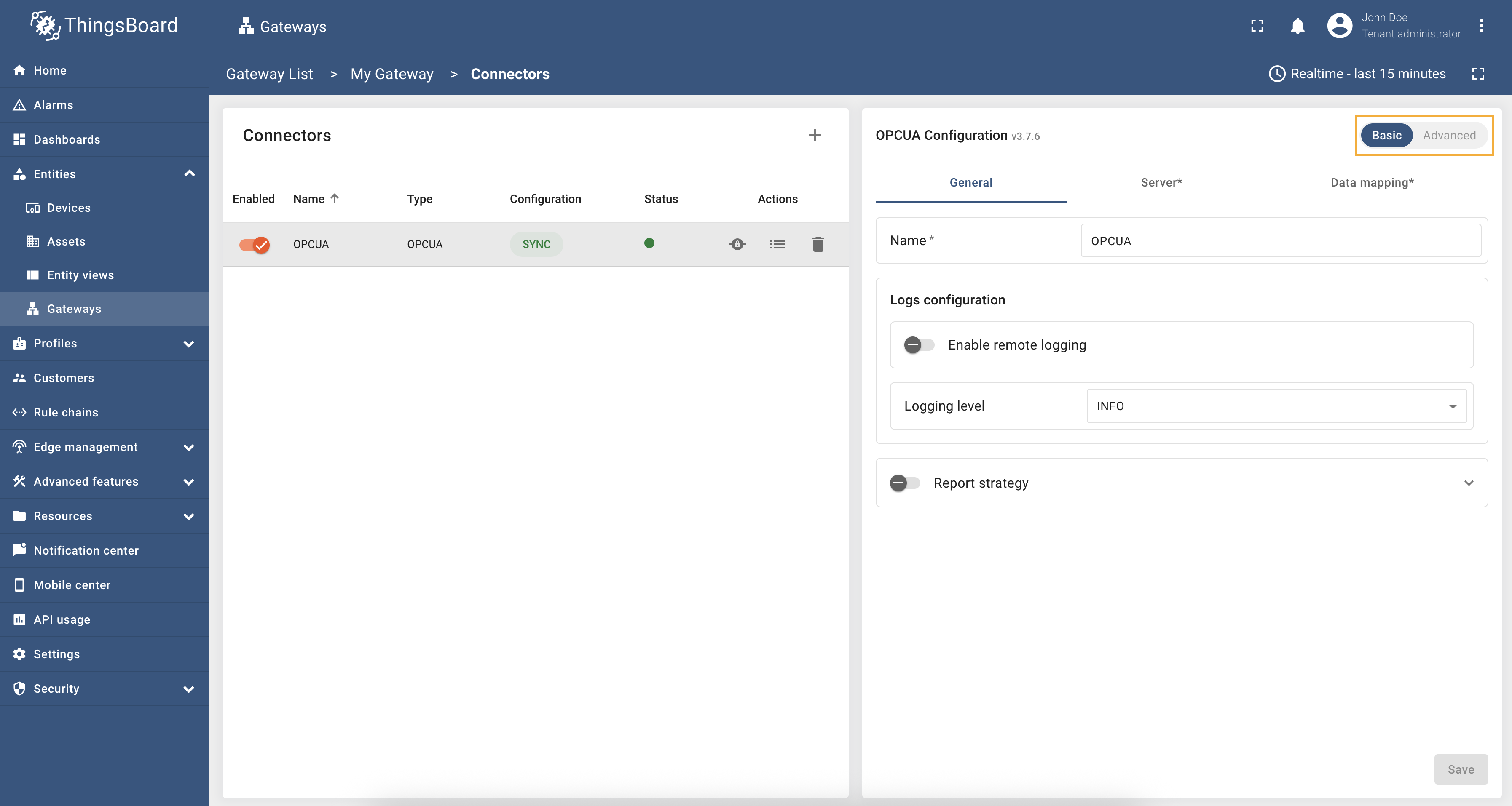
General settings
This configuration section contains general connector settings, such as:
- Name - connector name used for logs and saving to persistent devices;
- Logs configuration - settings for local and remote logging:
- Enable remote logging - enables remote logging for the connector;
- Logging level - logging level for local and remote logs: NONE, ERROR, CRITICAL, WARNING, INFO, DEBUG, TRACE;
- Report strategy - strategy for sending data to ThingsBoard:
- Report period - period for sending data to ThingsBoard in milliseconds;
- Type - type of the report strategy:
- On report period - sends data to ThingsBoard after the report period;
- On value change - sends data to ThingsBoard when the value changes;
- On value change or report period - sends data to ThingsBoard when the value changes or after the report period;
- On received - sends data to ThingsBoard after receiving data from the device (default strategy).
Additional information about the report strategy can be found here.

The General tab in settings is the same for both the basic and advanced configurations.
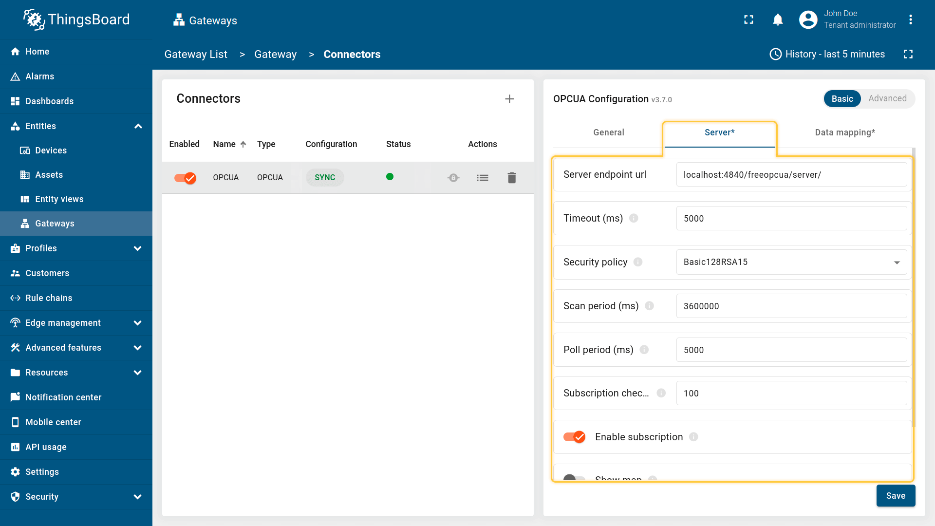
Connection settings
Connection settings define how the OPC-UA connector establishes and maintains communication with the OPC-UA server. These settings cover the basic connection parameters, server discovery behavior, security configuration, and authentication modes.
Server
This subsection specifies the target OPC-UA server and how the gateway interacts with it. It includes the server’s URL, timeout settings, scan intervals, and the option to use either subscriptions or polling to monitor data nodes.
This configuration section contains settings of the OPC-UA server connection, such as:
- Server endpoint url - hostname or ip address of OPC-UA server;
- Timeout in milliseconds - timeout in milliseconds for connecting to OPC-UA server;
- Security policy - security policy (Basic128Rsa15, Basic256, Basic256Sha256);
- Scan period in milliseconds - period in milliseconds to rescan the server;
- Poll period - period in milliseconds to poll the server;
- Subscription check period in milliseconds - period to check the subscriptions in the OPC-UA server;
- Enable subscription - if true - the gateway will subscribe to interesting nodes and wait for data update and if false - the gateway will rescan OPC-UA server every scanPeriodInMillis;
- Show map - show nodes on scanning true or false.
All configuration parameters list, and their detailed description can be found in the Advanced configuration section.
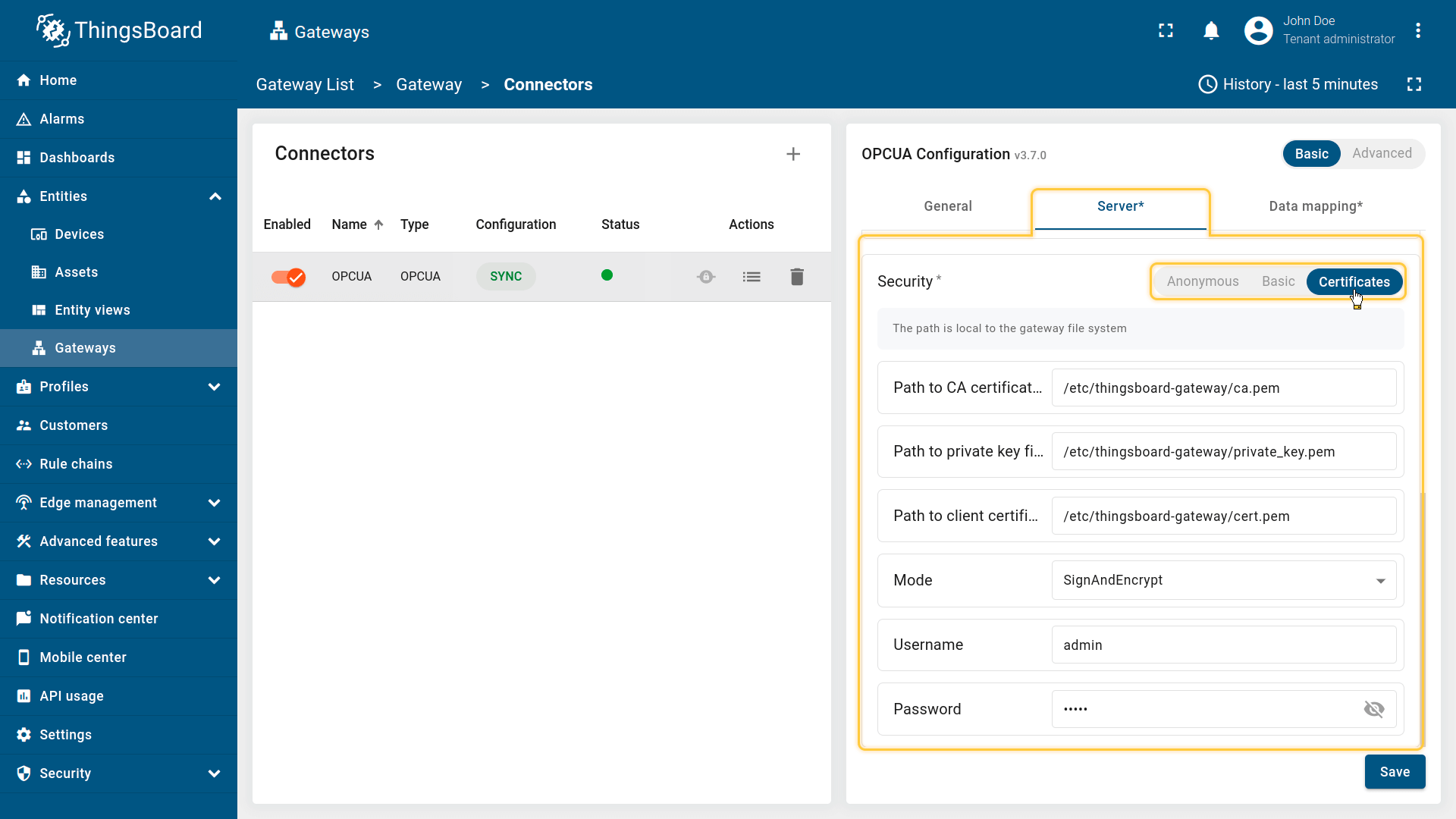
Security
OPC-UA server connections offer three distinct security types:
-
Anonymous - the simplest option of identity;
-
Basic - using this option, you can provide the username and password to connect to the OPC-UA server;
-
Certificates - the safest option of identity. Using this option, you can also provide path on machine with the gateway to certificate, private key and CA certificate. Optionally, you can provide the username/password pair.
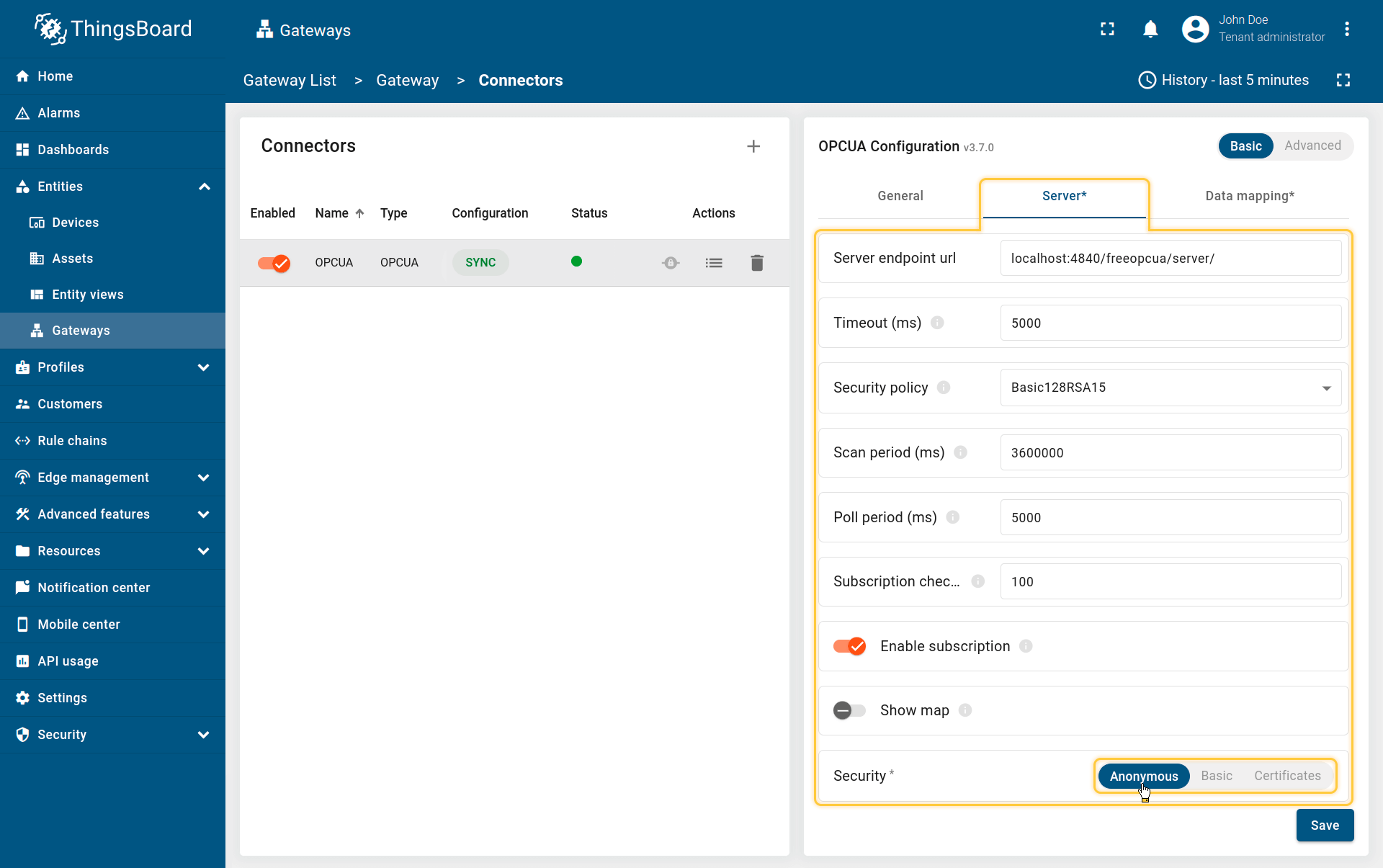
Anonymous - the simplest option of identity;
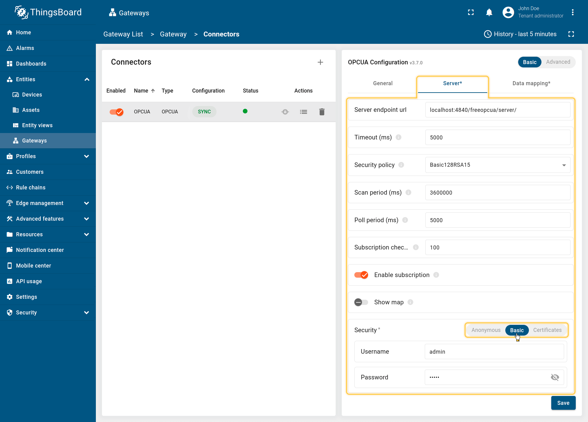
Basic - using this option, you can provide the username and password to connect to the OPC-UA server;
Certificates - the safest option of identity. Using this option, you can also provide path on machine with the gateway to certificate, private key and CA certificate. Optionally, you can provide the username/password pair.
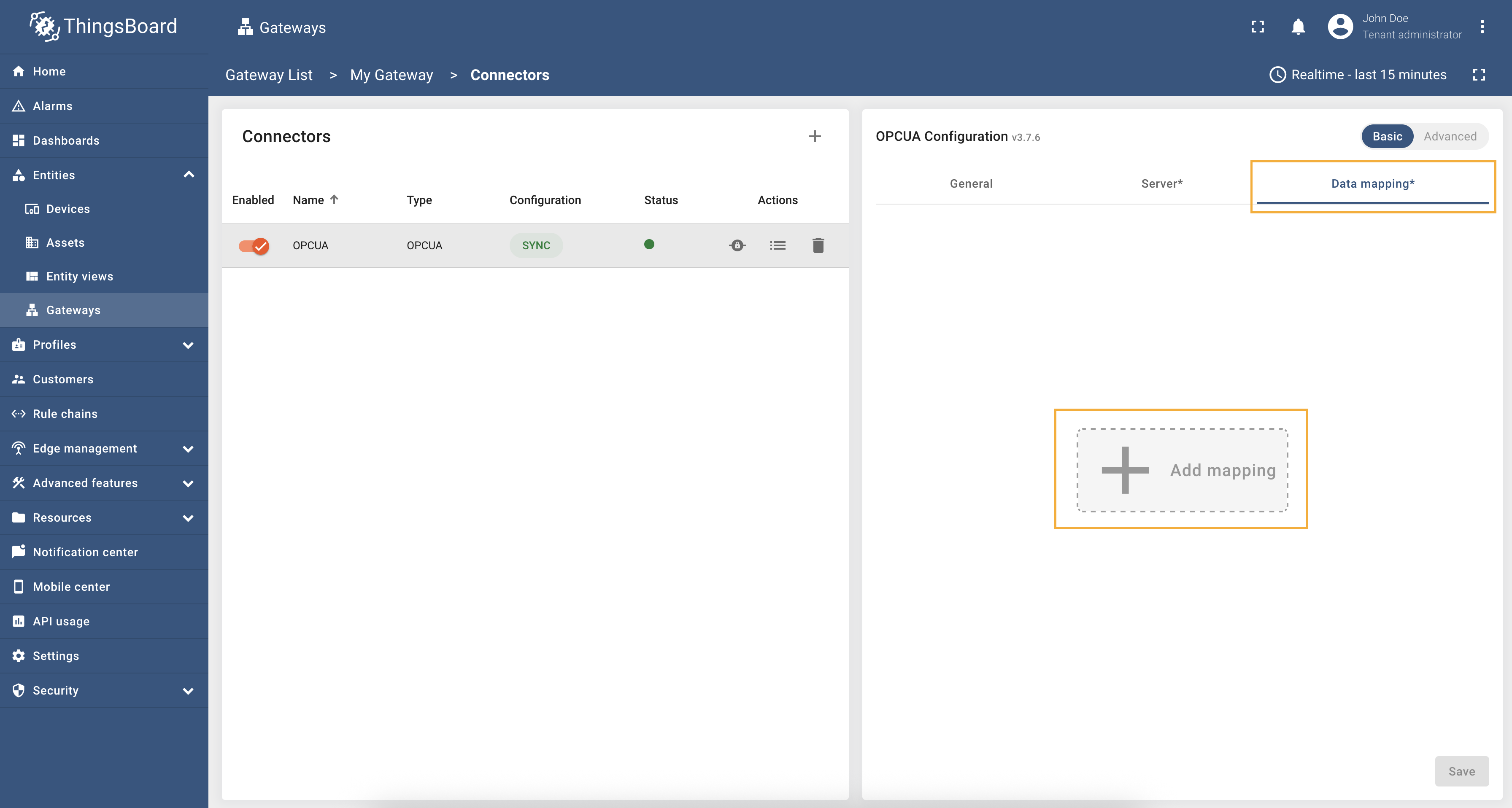
Data mapping
Data mapping is a section that allows you to configure which node from the OPC-UA server will be assigned to which device in ThingsBoard. You can also use this section to configure which data will be sent as device attributes or telemetry. Data mapping contains all the necessary settings for flexible device and data management.
The following parameters are used to configure the base node of the device, its name and profile, as well as for report strategy:
- Device node - the base node for the device. Paths to the device name, profile, attributes, and telemetry can be specified relative to this node.
- Device name - the name of the device in ThingsBoard. It can be specified as a path or identifier to the node or as a static value (more information about types can be found in the Additional information section).
- Device profile - the profile of the device in ThingsBoard. It can be specified as a path or identifier to the node or as a static value (more information about types can be found in the Additional information section).
- Report strategy - strategy for sending data to ThingsBoard:
- Report period - period for sending data to ThingsBoard in milliseconds;
- Type - type of the report strategy:
- On report period - sends data to ThingsBoard after the report period;
- On value change - sends data to ThingsBoard when the value changes;
- On value change or report period - sends data to ThingsBoard when the value changes or after the report period;
- On received - sends data to ThingsBoard after receiving data from the device (default strategy).
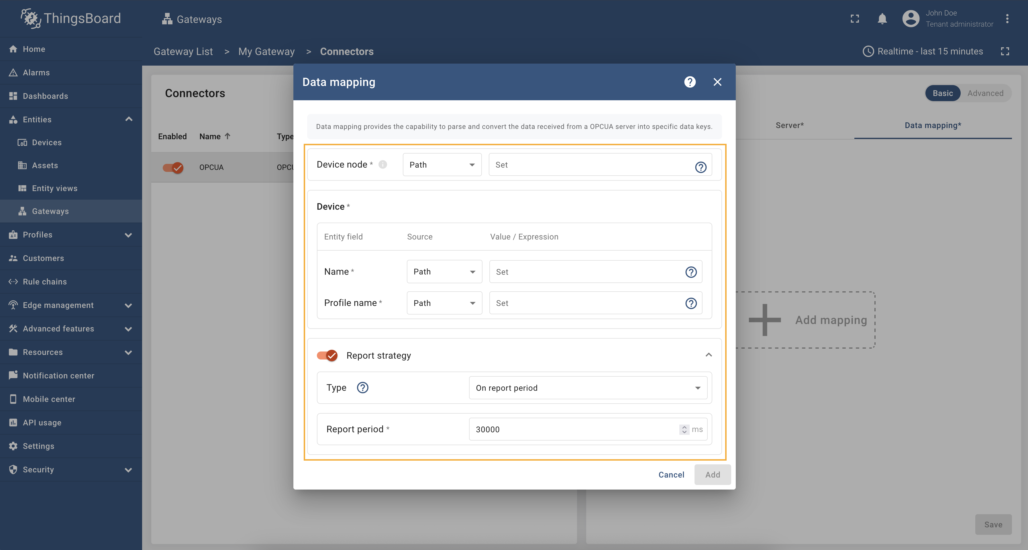
To add a new device, use the following steps:
-
Click the + Add mapping button.
-
Provide the following fields in the opened model window: Device node, Device name and Profile name (all of them can be
pathoridentifier).
Click the + Add mapping button.
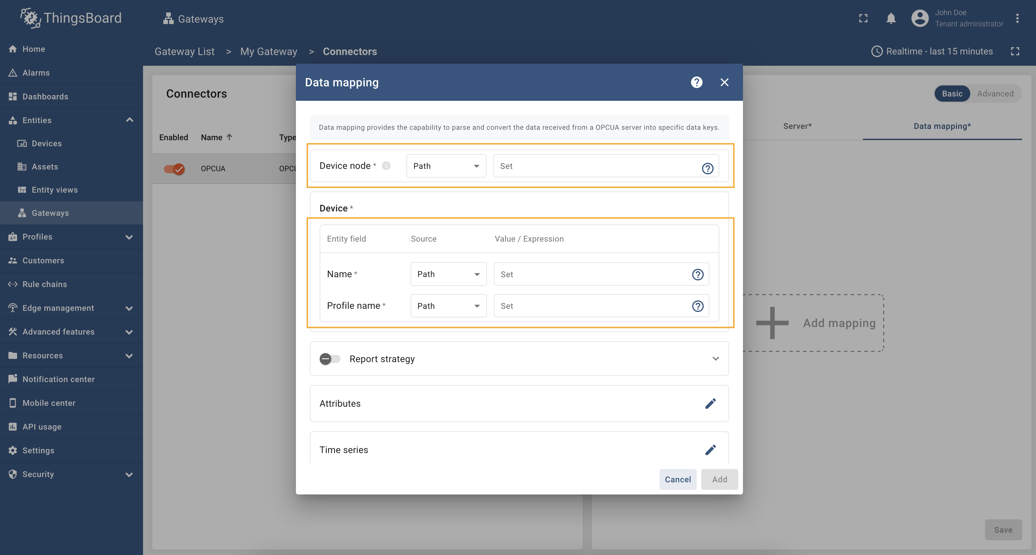
Provide the following fields in the opened model window: Device node, Device name and Profile name (all of them can be path or identifier).
Additional information about the report strategy can be found here.
All configuration parameters list, and their detailed description can be found in the Advanced configuration section.
More usage examples can be found in the Usage examples section.
Subsection “Attributes” and “Time series”
The configuration in this subsection provides settings for processing data from the OPC-UA node. These settings will be interpreted in ThingsBoard platform instance as attributes/time series of the device.
The following parameters are used to configure device attributes and time series:
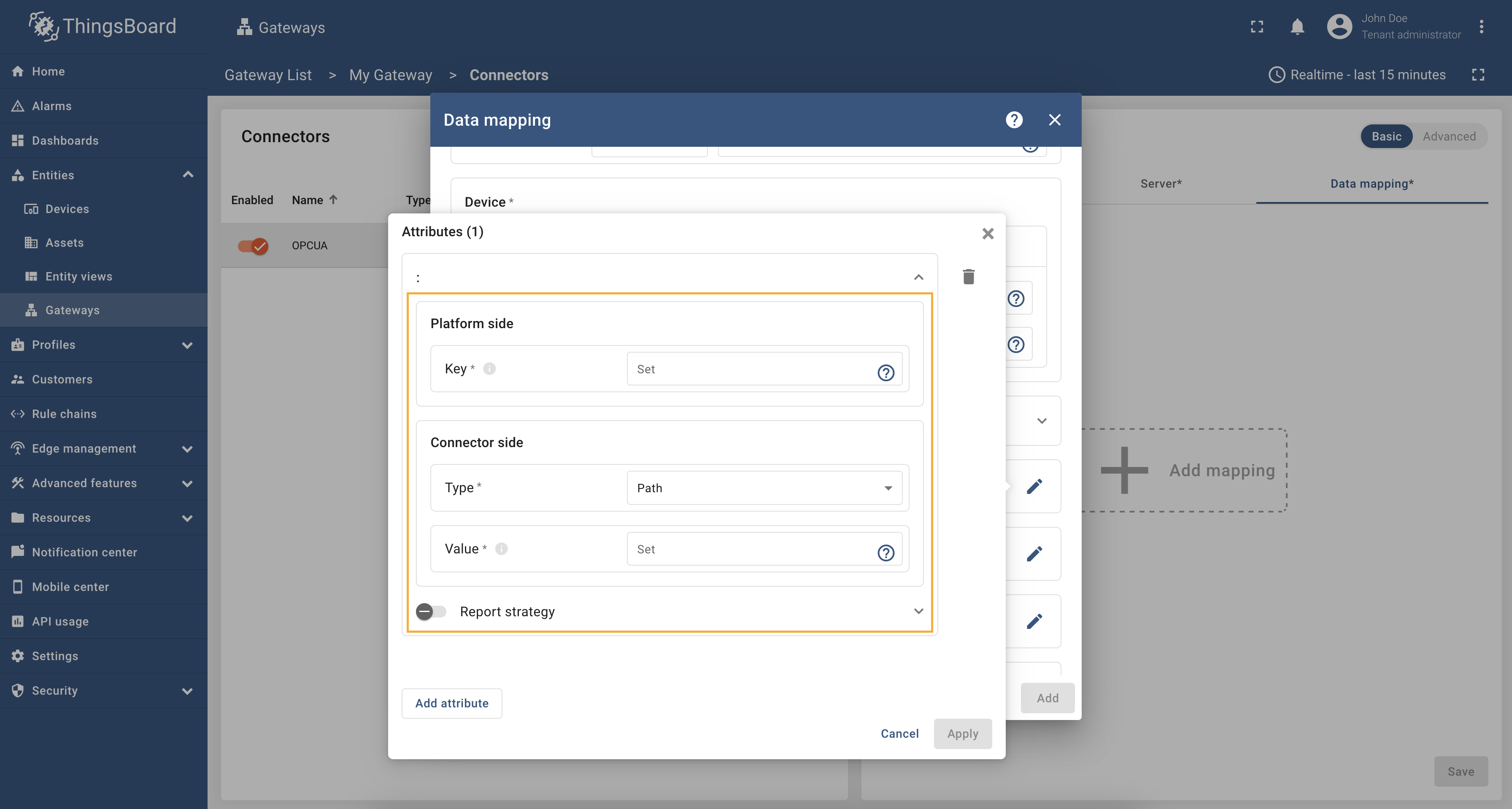
- Key - the key of the attribute/time series in ThingsBoard. It can be specified as a static value.
- Type - the type of expression in the Value field (more information about types can be found in the Additional information section):
- Path - can be absolute or relative path to the node in the OPC-UA server. The value will be taken from the node with the specified path.
- Identifier - can be numeric, string, byte string or GUID identifier of the node in the OPC-UA server. The value will be taken from the node with the specified identifier.
- Constant - a static value that will be sent to the device as an attribute/time series key.
- Value - the value of the attribute/time series that will be sent to the platform device. It should be specified depending on the selected type (Path, Identifier or Constant).
All configuration parameters list, and their detailed description can be found in the Advanced configuration section.
More usage examples can be found in the Usage examples section.
To add new time series or attribute key, follow these steps:
-
Click the “pencil” icon in the “Attributes” section to add new attribute key;
-
Click on “Add attribute” in the opened window;
-
Enter the “Key” field, select the “Type” (can be path, identifier or constant), enter “Value” and click “Apply” button;
-
Now click on the “pencil” icon in the “Time series” section to add new time series key;
-
Click on “Add time series” in the opened window;
-
Enter the “Key” field, select the “Type” (can be path, identifier or constant), enter “Value” and click “Apply” button.
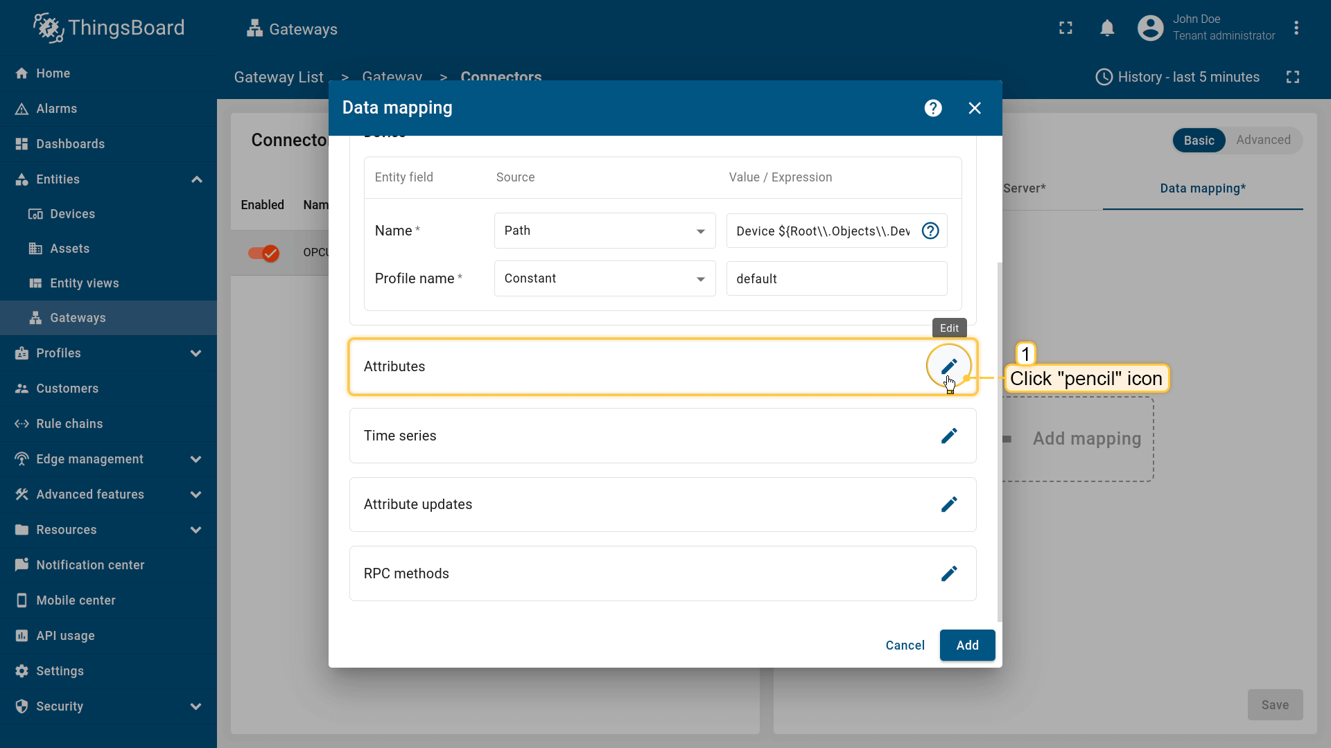
Click the “pencil” icon in the “Attributes” section to add new attribute key;
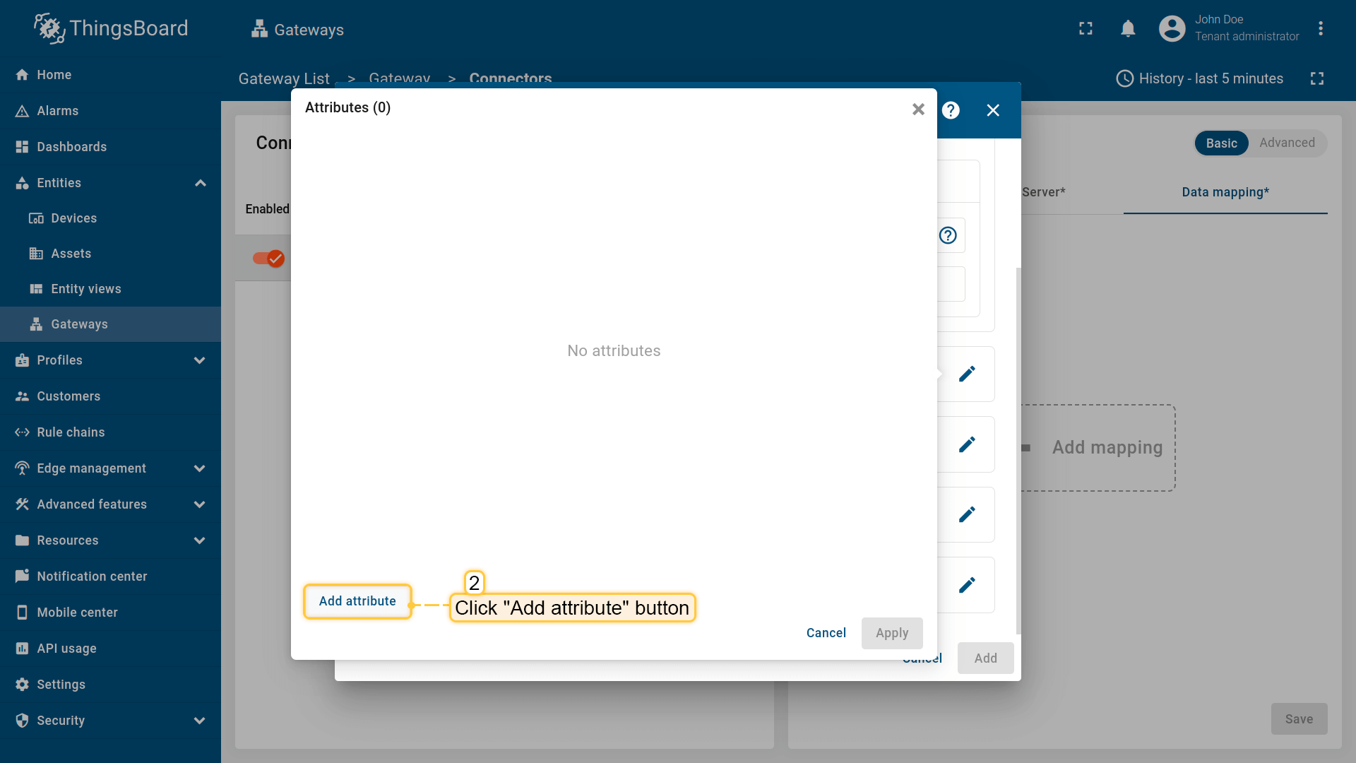
Click on “Add attribute” in the opened window;
, [identifier](#identifier-types) or constant), enter "Value" and click "Apply" button;](/images/gateway/opc-ua-connector/opc-ua-gateway-configuring-5-ce.png)
Enter the “Key” field, select the “Type” (can be path, identifier or constant), enter “Value” and click “Apply” button;
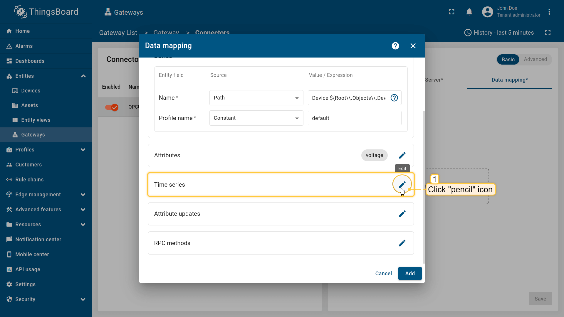
Now click on the “pencil” icon in the “Time series” section to add new time series key;
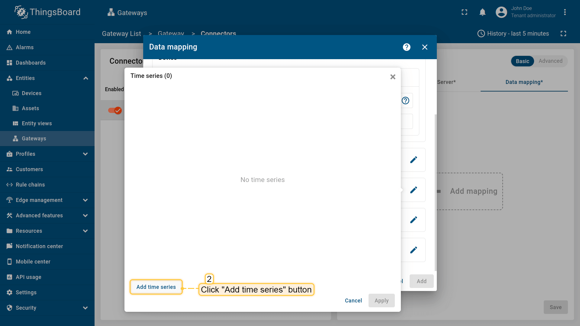
Click on “Add time series” in the opened window;
, [identifier](#identifier-types) or constant), enter "Value" and click "Apply" button.](/images/gateway/opc-ua-connector/opc-ua-gateway-configuring-8-ce.png)
Enter the “Key” field, select the “Type” (can be path, identifier or constant), enter “Value” and click “Apply” button.
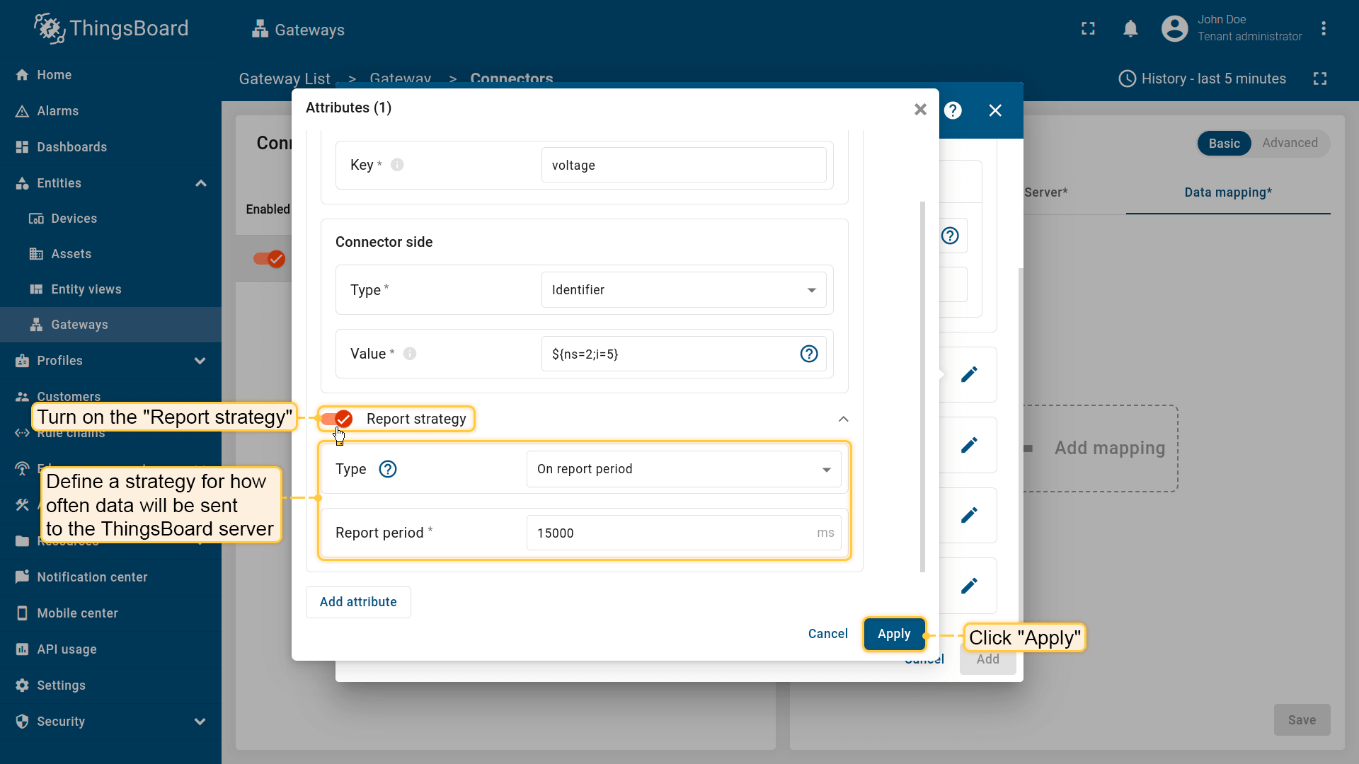
You can enable a specific report strategy for each time series or attribute. This strategy defines how often
data is sent to the ThingsBoard server. The following strategies are available:
- On report period - sends data to ThingsBoard after the report period;
- On value change - sends data to ThingsBoard when the value changes;
- On value change or report period - sends data to ThingsBoard when the value changes or after the report period;
- On received - sends data to ThingsBoard after receiving data from the device (default strategy).
Additional information about the report strategy can be found here.
Usage examples
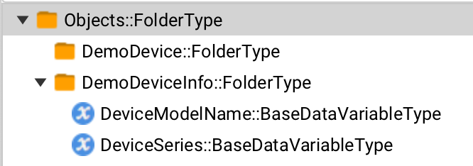
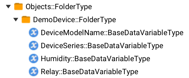
The device name and profile can be set dynamically using node values. In this example, we will use an absolute path to specify the device name and profile. As an example, we will use Prosys OPC-UA Simulation Server, which is available at
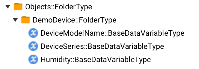
We are interested in nodes: “DeviceModelName” and “DeviceSeries”. We will use these nodes to set the device name and profile, respectively. Let’s configure the device name and profile in the OPC-UA connector. For this purpose, follow these steps:
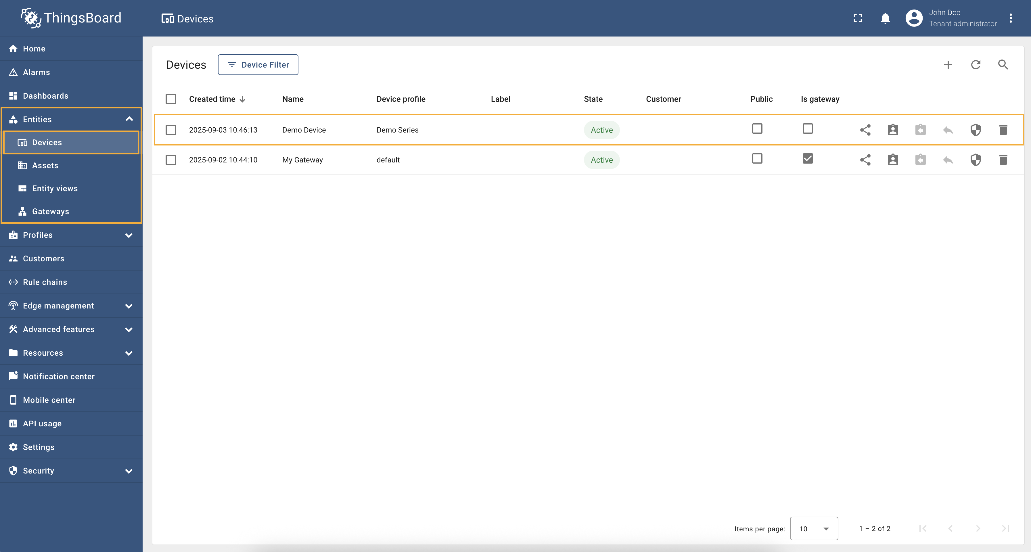
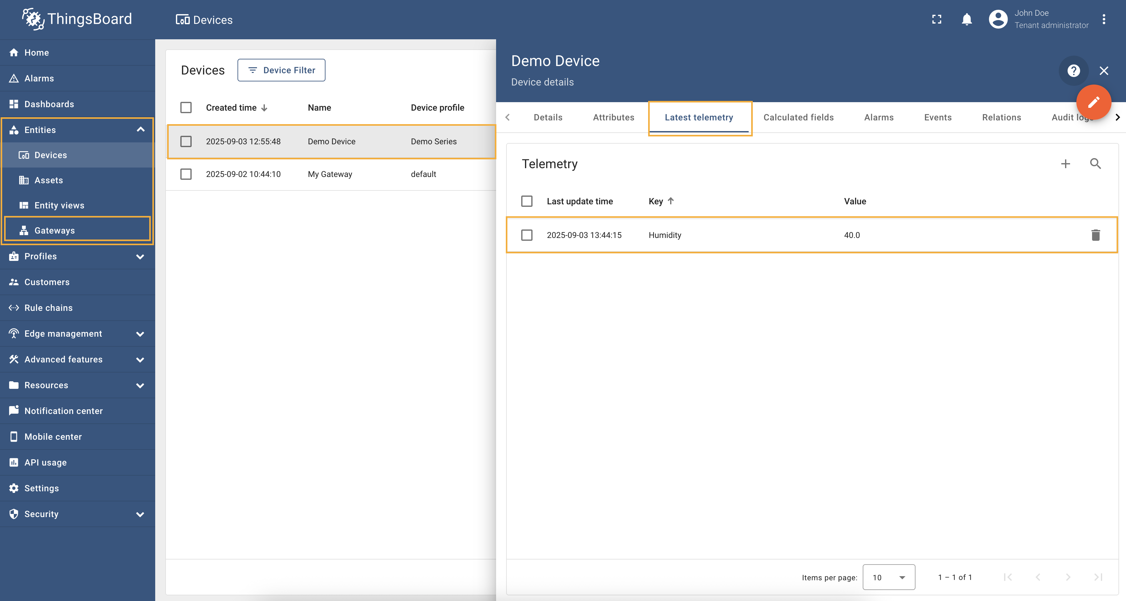
 Go to “Entities” → “Gateways” in the right sidebar and select your gateway. 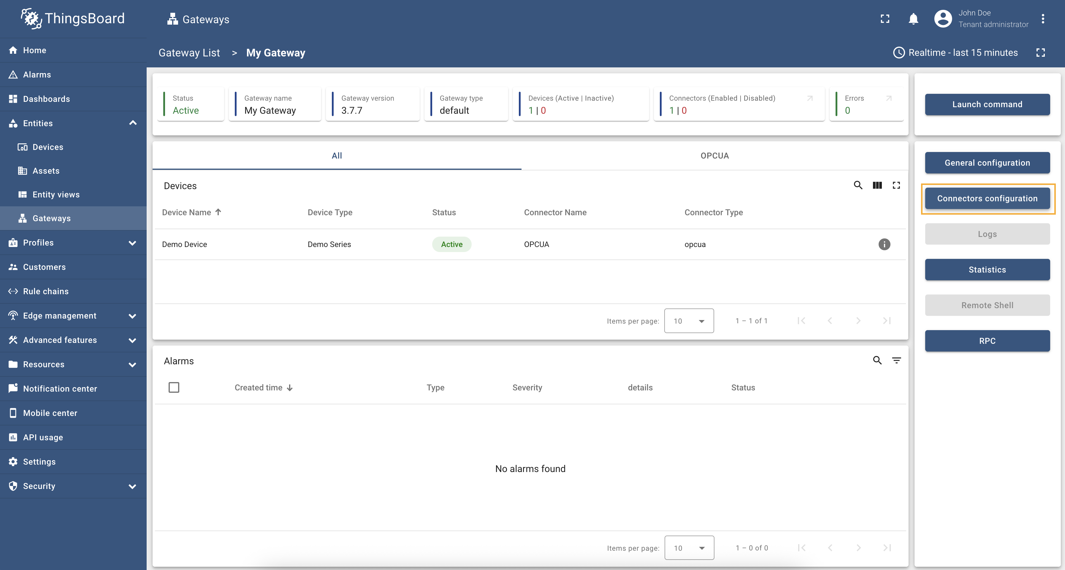 Click on the “Connectors configuration” button on the right side menu. 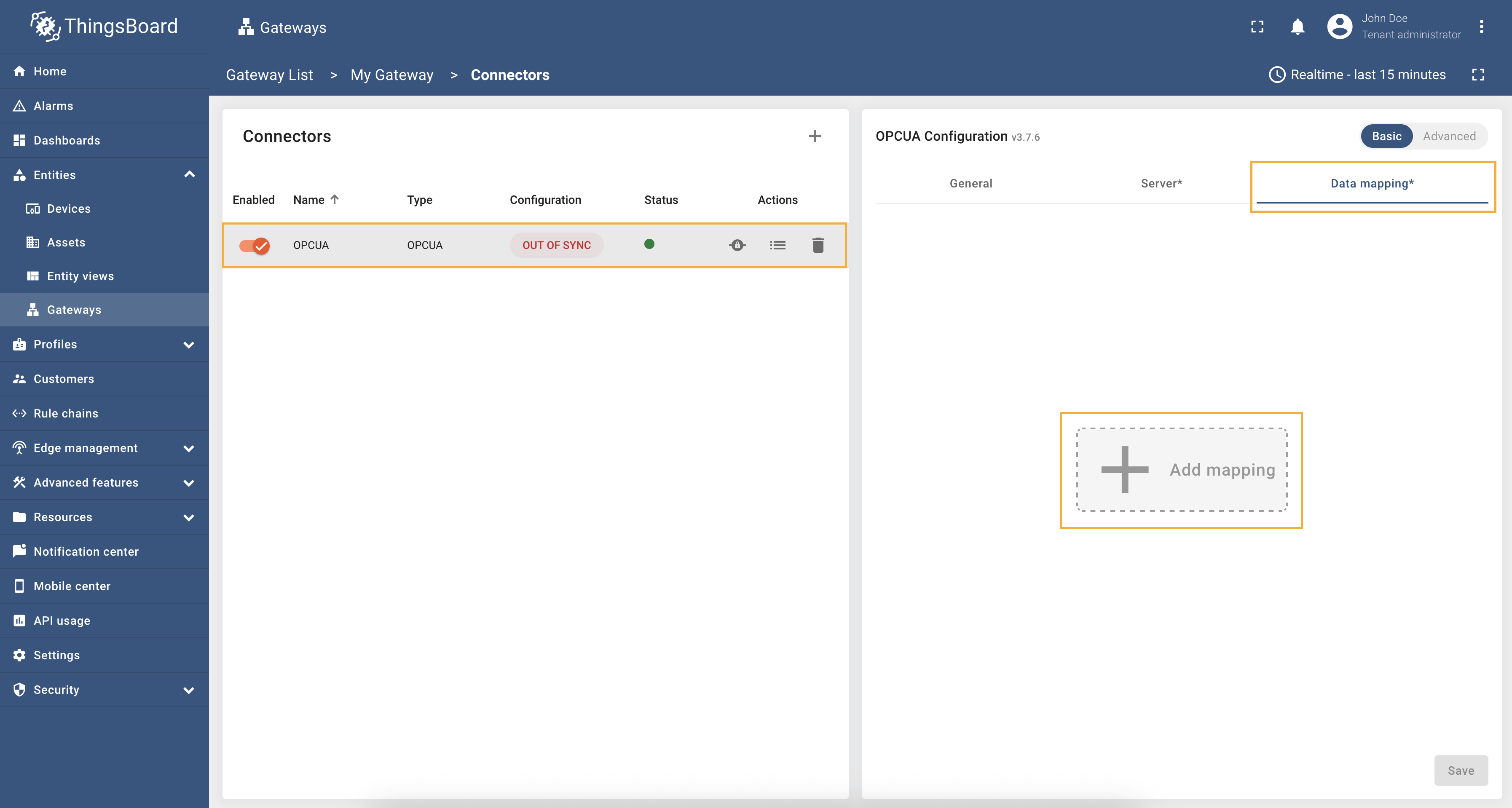 Select the created OPC-UA connector, click on the “Data mapping” tab. Firstly, we need to configure parent (or device) node. Click on the “+ Add mapping” button. " in "Source" field. This is an absolute path to the parent node of the device we want to create.](/images/gateway/opc-ua-connector/examples/device-name-and-profile-absolute-path-4.png) In the opened window, fill in “Device node” field with " in "Source" field. This is an absolute path to the node that contains the device name.](/images/gateway/opc-ua-connector/examples/device-name-and-profile-absolute-path-5.png) In the “Name” field, enter " in "Source" field. This is an absolute path to the node that contains the device profile.](/images/gateway/opc-ua-connector/examples/device-name-and-profile-absolute-path-6.png) In the “Profile name” field, enter 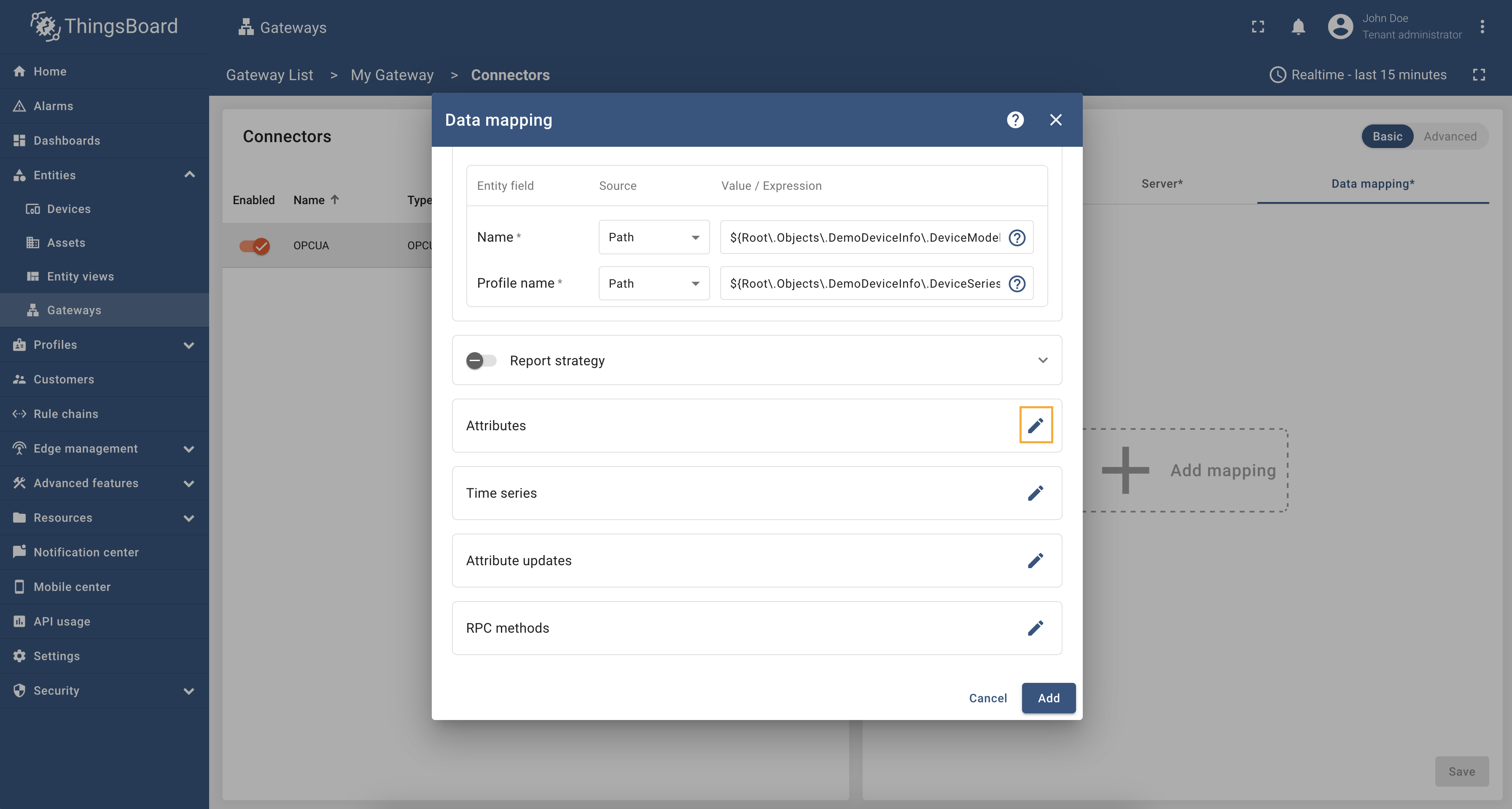 Also, we need to add one attribute/time series because the connector will not add a device without any data to read (you can use any pre-installed Prosys OPC-UA Simulation Server node). Click on the “pencil” icon next to the “Attributes” section. 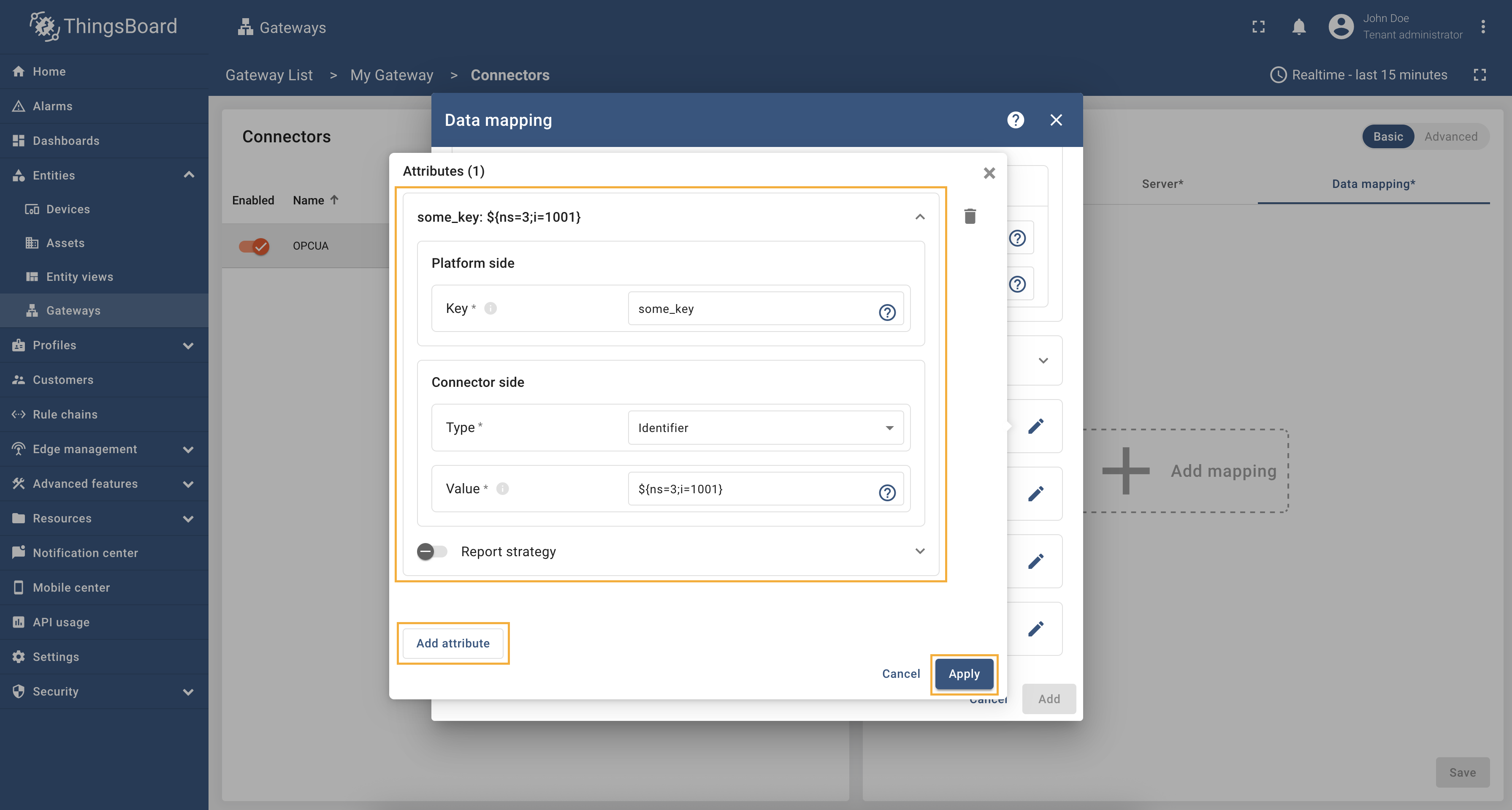 In the opened window, click on the “Add attribute” button and fill the fields as on the corresponding image. 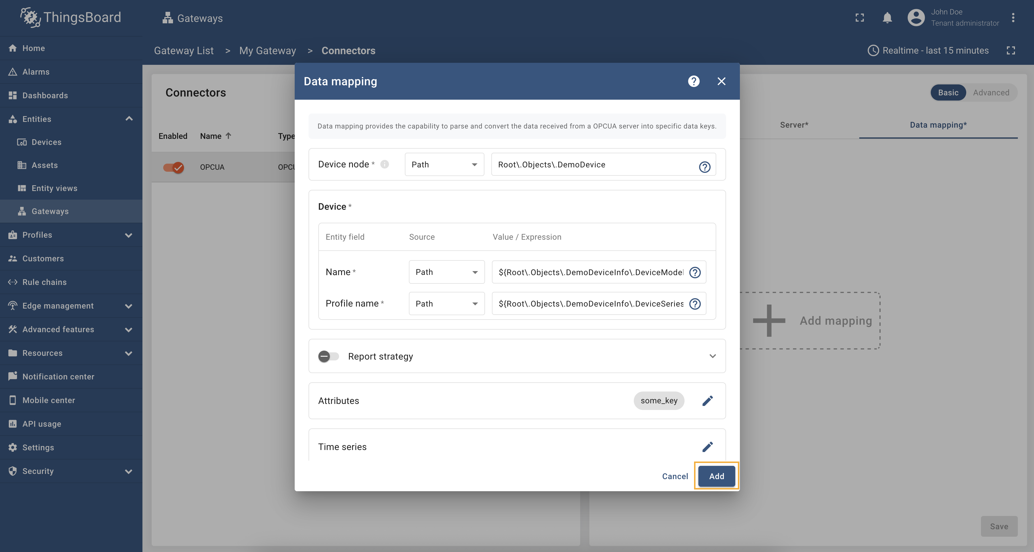 Remember to save your changes by clicking the “Save” button. Now we can check if the device name and profile are set correctly. Go to “Entities” > “Devices” and as you can see, the device
name is set to
If you are using advanced configuration mode and want to set the device name and profile using an absolute path, you can use the following configuration: |
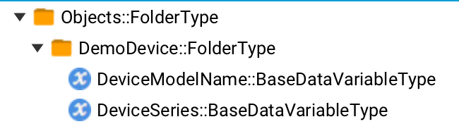
The device name and profile can be set dynamically using node values. In this example, we will use a relative path to specify the device name and profile. As an example, we will use Prosys OPC-UA Simulation Server, which is available at
We are interested in nodes: “DeviceModelName” and “DeviceSeries”. We will use these nodes to set the device name and profile, respectively. Let’s configure the device name and profile in the OPC-UA connector. For this purpose, follow these steps:
Go to “Entities” → “Gateways” in the right sidebar and select your gateway. Click on the “Connectors configuration” button on the right side menu. Select the created OPC-UA connector, click on the “Data mapping” tab. Firstly, we need to configure parent (or device) node. Click on the “+ Add mapping” button. In the opened window, fill in “Device node” field with " in "Source" field. This is a relative path to the node that contains the device name.](/images/gateway/opc-ua-connector/examples/device-name-and-profile-relative-path-5.png) In the “Name” field, enter " in "Source" field. This is a relative path to the node that contains the device profile.](/images/gateway/opc-ua-connector/examples/device-name-and-profile-relative-path-6.png) In the “Profile name” field, enter 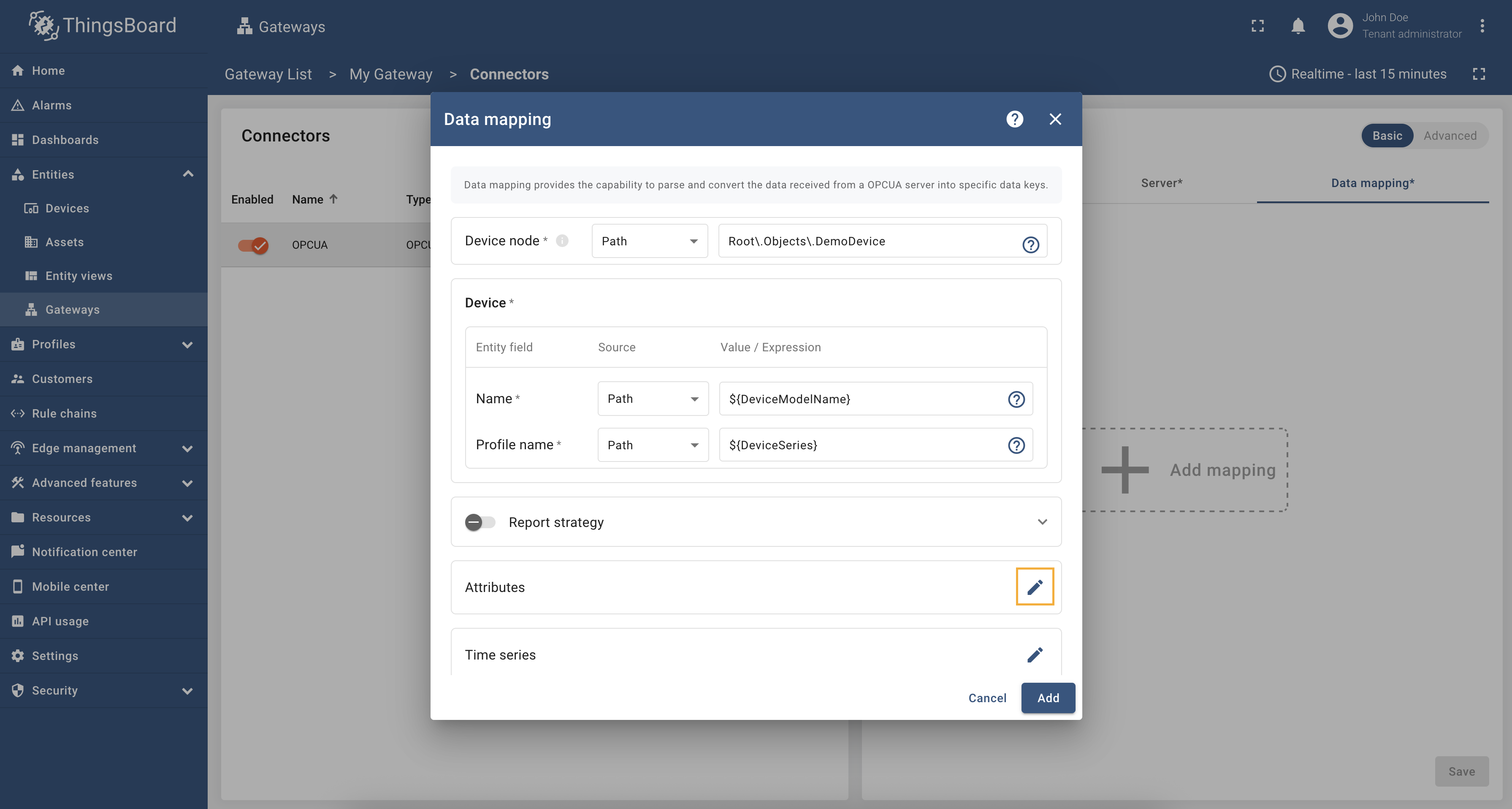 Also, we need to add one attribute/time series because the connector will not add a device without any data to read (you can use any pre-installed Prosys OPC-UA Simulation Server node). Click on the “pencil” icon next to the “Attributes” section. In the opened window, click on the “Add attribute” button and fill the fields as on the corresponding image.  Remember to save your changes by clicking the “Save” button. Now we can check if the device name and profile are set correctly. Go to “Entities” > “Devices” and as you can see, the device
name is set to
If you are using advanced configuration mode and want to set the device name and profile using a relative path, you can use the following configuration: |
The device name and profile can be set dynamically using node values. In this example, we will use identifier to specify the device name and profile. Identifier can be numeric, string, byte string or GUID identifier of the node in the OPC-UA server. As an example, we will use Prosys OPC-UA Simulation Server, which is available at
We are interested in nodes: “DeviceModelName” that have Let’s configure the device name and profile in the OPC-UA connector. For this purpose, follow these steps:
Go to “Entities” → “Gateways” in the right sidebar and select your gateway. Click on the “Connectors configuration” button on the right side menu. Select the created OPC-UA connector, click on the “Data mapping” tab. Firstly, we need to configure parent (or device) node. Click on the “+ Add mapping” button. In the opened window, fill in “Device node” field with " in "Source" field.](/images/gateway/opc-ua-connector/examples/device-name-and-profile-identifier-path-5.png) In the “Name” field, enter " in "Source" field. This is an absolute path to the node that contains the device profile.](/images/gateway/opc-ua-connector/examples/device-name-and-profile-identifier-path-6.png) In the “Profile name” field, enter 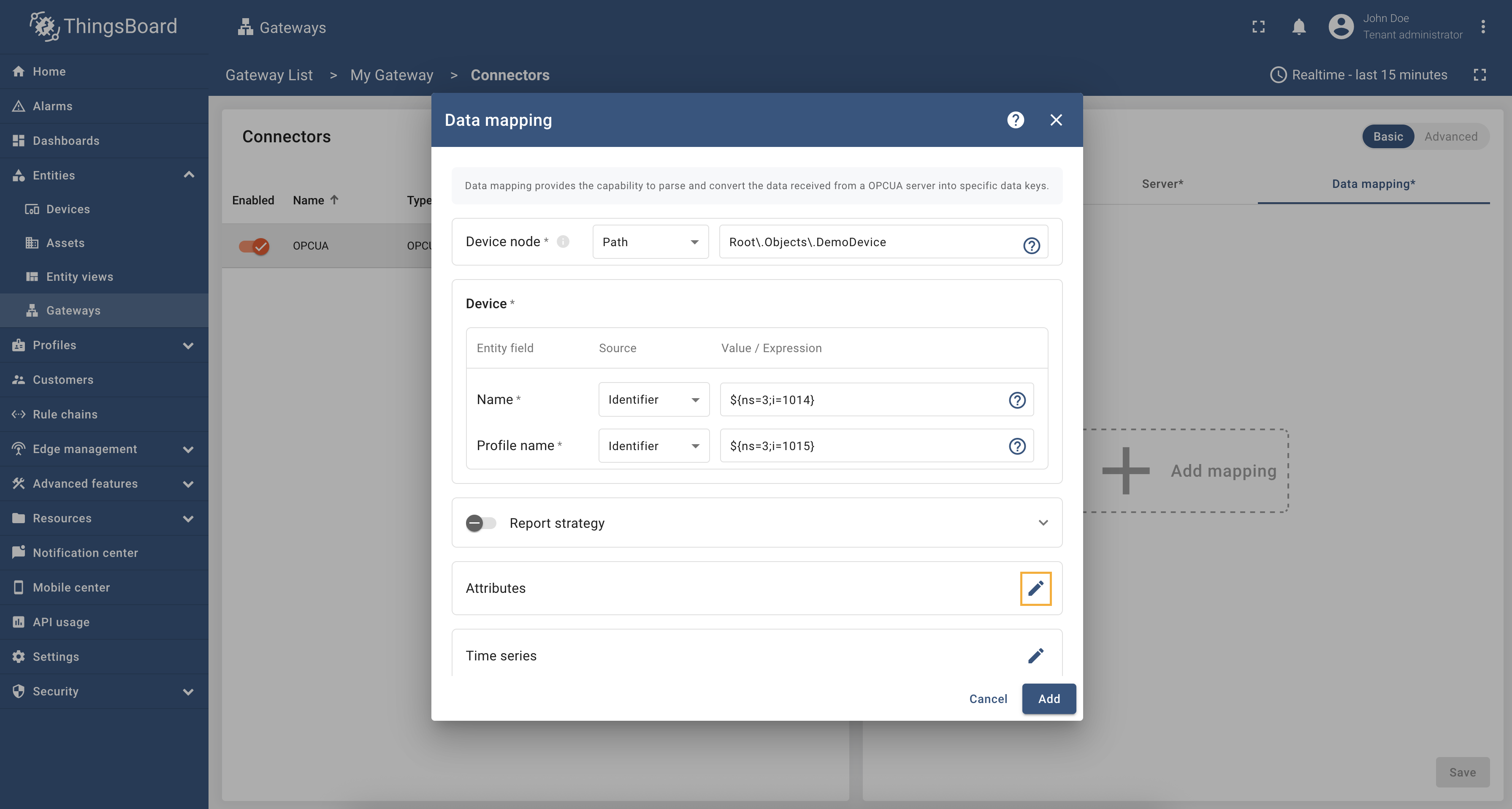 Also, we need to add one attribute/time series because the connector will not add a device without any data to read (you can use any pre-installed Prosys OPC-UA Simulation Server node). Click on the “pencil” icon next to the “Attributes” section. In the opened window, click on the “Add attribute” button and fill the fields as on the corresponding image.  Remember to save your changes by clicking the “Save” button. Now we can check if the device name and profile are set correctly. Go to “Entities” > “Devices” and as you can see, the device
name is set to
If you are using advanced configuration mode and want to set the device name and profile using an identifier, you can use the following configuration: |
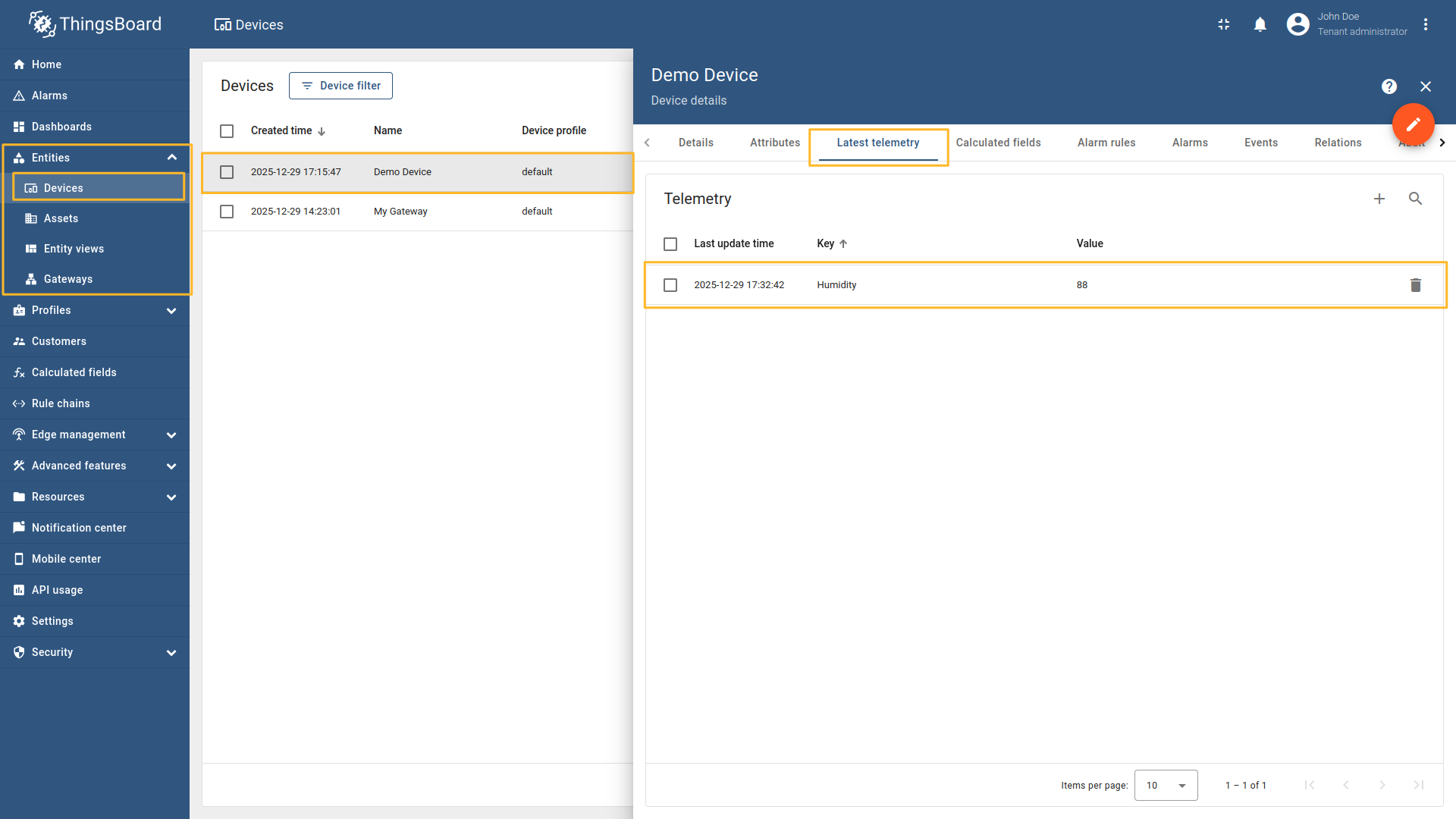
Attributes and time series data can be accessed using relative paths in the OPC UA Connector. This allows you to retrieve data without needing to specify the full path to the node. As an example, we will use Prosys OPC-UA Simulation Server, which is available at
We are interested in node “Humidity”. We will use this node to retrieve the humidity data. Let’s configure the humidity data in the OPC-UA connector. For this purpose, follow these steps:
Go to “Entities” → “Gateways” in the right sidebar and select your gateway. Click on the “Connectors configuration” button on the right side menu. {:target="_blank"} guide or [Data mapping](/docs/iot-gateway/config/opc-ua/#data-mapping) section of this guide with respective examples).](/images/gateway/opc-ua-connector/examples/attributes-time-series-absolute-path-1.png) Select the OPC-UA connector, click on the “Data mapping” tab. Select data mapping with device to which you want to add time series data (if you do not know how to add a new device, see the Getting Started guide or Data mapping section of this guide with respective examples).  In the opened data mapping windows, click on the “pencil” icon next to the “Time series” or “Attributes” section. " in "Type" field, and fill in the "Value" field with `${Humidity}`. This is a relative path to the node that contains the humidity data.](/images/gateway/opc-ua-connector/examples/attributes-time-series-relative-path-3.png) Click on the “Add time series” button. Fill in the “Key” field with 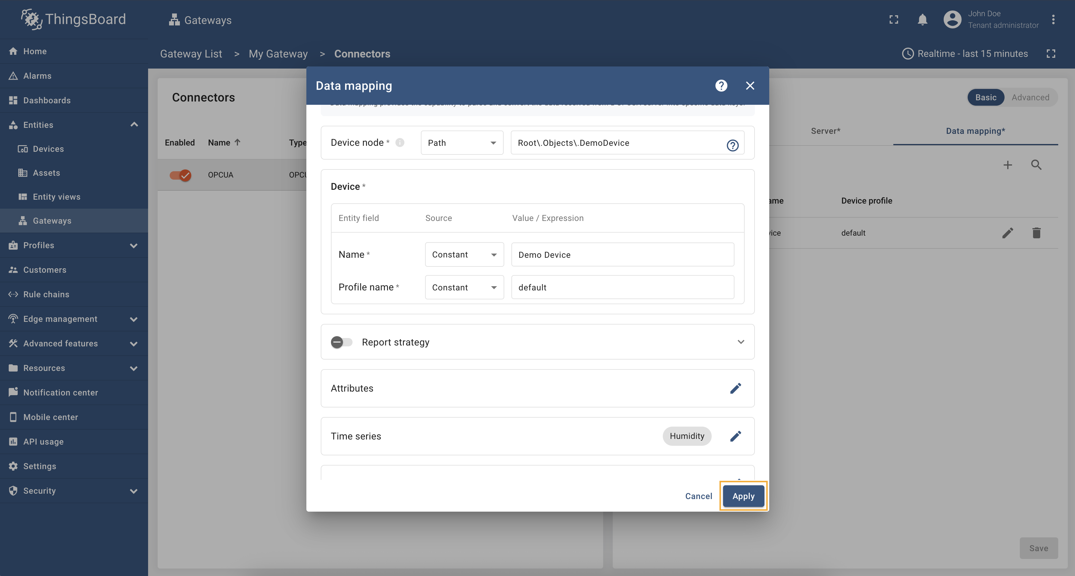 Remember to save your changes by clicking the “Apply” button. Now we can check if the humidity data is sending correctly. Go to “Entities” > “Devices”, select a created device and as you can see, the humidity data is available in the “Time series” section:
If you are using advanced configuration mode and want to set the humidity data using a relative path, you can use the following configuration: |
Attributes and time series data can be accessed using relative paths in the OPC UA Connector. This allows you to retrieve data without needing to specify the full path to the node. Additionally, we may use identifiers for “Device node”. As an example, we will use Prosys OPC-UA Simulation Server, which is available at
We are interested in node “Humidity”. We will use this node to retrieve the humidity data. Let’s configure the humidity data in the OPC-UA connector, using relative paths. For this purpose, follow these steps:
Go to “Entities” → “Gateways” in the left sidebar and select your gateway. Click on the “Connectors configuration” button on the right side menu. {:target="_blank"} guide or [Data mapping](/docs/iot-gateway/config/opc-ua/#data-mapping) section of this guide with respective examples).](/images/gateway/opc-ua-connector/examples/attributes-time-series-relative-path-device-identifier-1.png) Select the OPC-UA connector, click on the “Data mapping” tab. Select data mapping with device to which you want to add time series data (if you do not know how to add a new device, see the Getting Started guide or Data mapping section of this guide with respective examples). 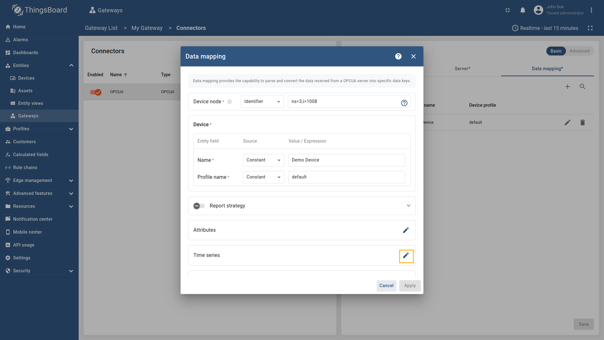 In the opened data mapping windows, click on the “pencil” icon next to the “Time series” or “Attributes” section. Click on the “Add time series” button. Fill in the “Key” field with 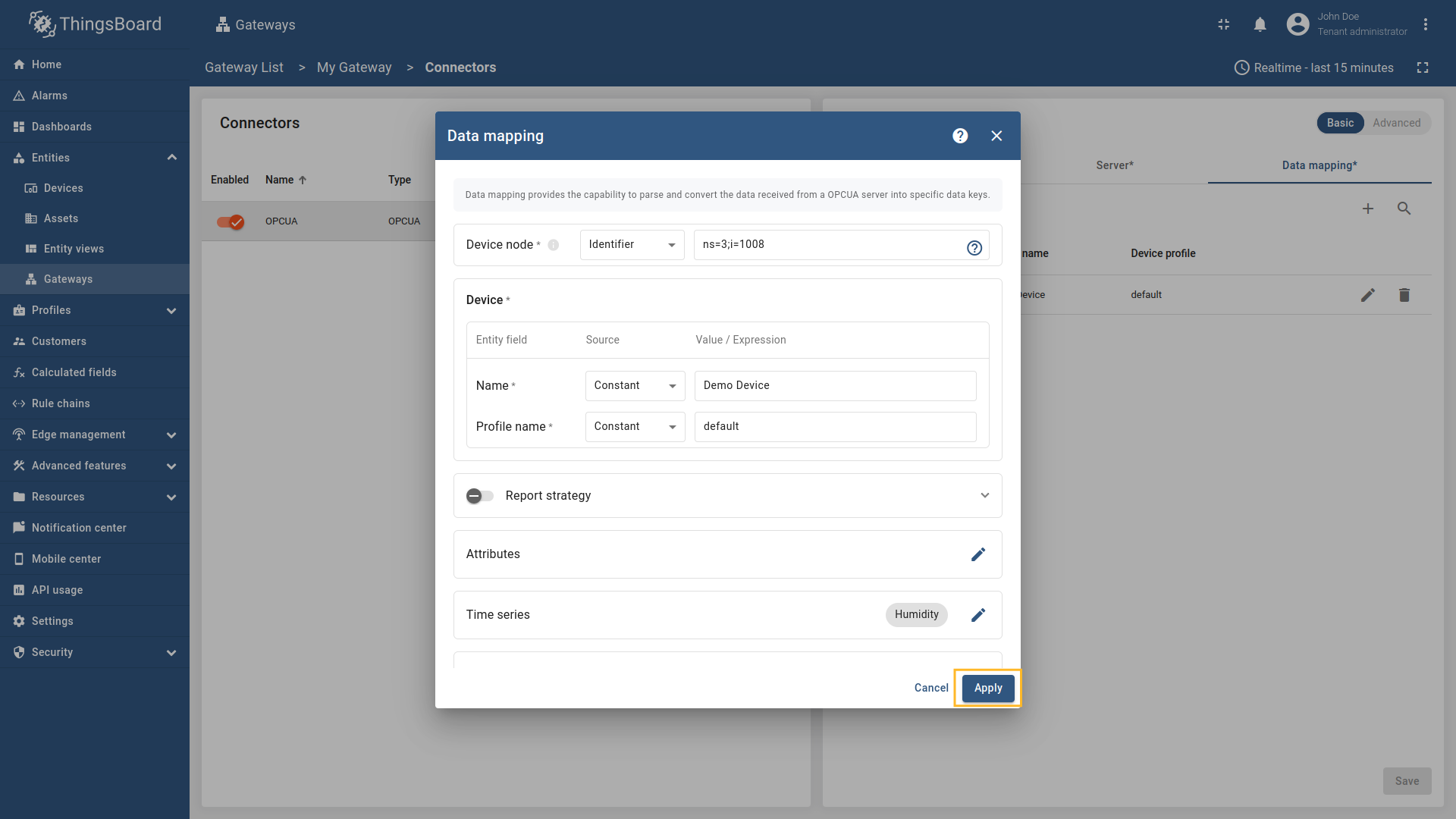 Remember to save your changes by clicking the “Apply” button. Now we can check if the humidity data is sending correctly. Go to “Entities” > “Devices”, select a created device and as you can see, the humidity data is available in the “Time series” section:
If you are using advanced configuration mode and want to set the humidity data using a relative path, you can use the following configuration: |
Attributes and time series data can be accessed using absolute paths in the OPC UA Connector. This will allow you to get data from a node that does not refer to the parent (device) node. As an example, we will use Prosys OPC-UA Simulation Server, which is available at
We are interested in node “Humidity”. We will use this node to retrieve the humidity data. Let’s configure the humidity data in the OPC-UA connector. For this purpose, follow these steps:
Go to “Entities” → “Gateways” in the right sidebar and select your gateway. Click on the “Connectors configuration” button on the right side menu. Select the OPC-UA connector, click on the “Data mapping” tab. Select data mapping with device to which you want to add time series data (if you do not know how to add a new device, see the Getting Started guide or Data mapping section of this guide with respective examples). In the opened data mapping windows, click on the “pencil” icon next to the “Time series” or “Attributes” section. " in "Type" field, and fill in the "Value" field with `${Root\.Objects\.DemoDevice\.Humidity}`. This is an absolute path to the node that contains the humidity data.](/images/gateway/opc-ua-connector/examples/attributes-time-series-absolute-path-3.png) Click on the “Add time series” button. Fill in the “Key” field with Remember to save your changes by clicking the “Apply” button. Now we can check if the humidity data is sending correctly. Go to “Entities” > “Devices”, select a created device and as you can see, the humidity data is available in the “Time series” section:
If you are using advanced configuration mode and want to set the humidity data using an absolute path, you can use the following configuration: |
Attributes and time series data can be accessed using identifiers in the OPC UA Connector. This will allow you to get data from a node that does not refer to the parent (device) node by identifier. As an example, we will use Prosys OPC-UA Simulation Server, which is available at
We are interested in node “Humidity” that have Let’s configure the humidity data in the OPC-UA connector. For this purpose, follow these steps:
Go to “Entities” → “Gateways” in the left sidebar and select your gateway. Click on the “Connectors configuration” button on the right side menu. Select the OPC-UA connector, click on the “Data mapping” tab. Select data mapping with device to which you want to add time series data (if you do not know how to add a new device, see the Getting Started guide or Data mapping section of this guide with respective examples). In the opened data mapping windows, click on the “pencil” icon next to the “Time series” or “Attributes” section. " in "Type" field, and fill in the "Value" field with `${ns=3;i=1011}`. This is a relative path to the node that contains the humidity data.](/images/gateway/opc-ua-connector/examples/attributes-time-series-identifier-path-3.png) Click on the “Add time series” button. Fill in the “Key” field with Remember to save your changes by clicking the “Apply” button. Now we can check if the humidity data is sending correctly. Go to “Entities” > “Devices”, select a created device and as you can see, the humidity data is available in the “Time series” section:
If you are using advanced configuration mode and want to set the humidity data using an identifier, you can use the following configuration: |
Requests mapping
The Requests mapping section allows you to configure how the ThingsBoard platform instance will interact with the devices. That is, how the platform will request data from the devices, how it will update device attributes, and how it will send RPC commands to the devices.
OPC-UA connector supports the following requests mapping:
- Attribute updates - allows update device nodes values from ThingsBoard platform instance.
- RPC methods - allows sending RPC commands to devices. Using RPC methods, you can get or set values of the OPC-UA nodes.
OPC-UA connector supports different types of RPC methods, such as:
- Reserved GET/SET methods - these methods are automatically created for each attribute and time series parameter. You can use them to get or set values of the OPC-UA nodes.
- RPC method to connector - this method allows you to send a command to the connector from the ThingsBoard IoT Gateway UI. The command will be processed by the connector, and the result will be sent back to the ThingsBoard platform instance.
- Configurable RPC methods to device - these methods allow you to configure custom RPC commands in connector configuration that can be sent to the devices.
Subsection “Attribute updates”
This subsection contains configuration for attribute updates request from ThingsBoard platform instance.
ThingsBoard allows the provisioning of device attributes and fetches some of them from the device application. You can treat this as a remote configuration for devices, enabling them to request shared attributes from ThingsBoard. See user guide for more details.
The following parameters are used to configure attribute updates:
- Key - the key of the shared attribute in ThingsBoard. It can be specified as a static value.
- Type - the type of expression in the Value field (more information about types can be found in the Additional information section):
- Path - can be absolute or relative path to the node in the OPC-UA server. The value will be taken from the node with the specified path.
- Identifier - can be numeric, string, byte string or GUID identifier of the node in the OPC-UA server. The value will be taken from the node with the specified identifier.
- Constant - a static value that will be sent to the device.
- Value - the node in which the shared attribute value will be written. It should be specified depending on the selected type (Path, Identifier or Constant).
All configuration parameters list, and their detailed description can be found in the Advanced configuration section.
More usage examples can be found in the Usage examples section.
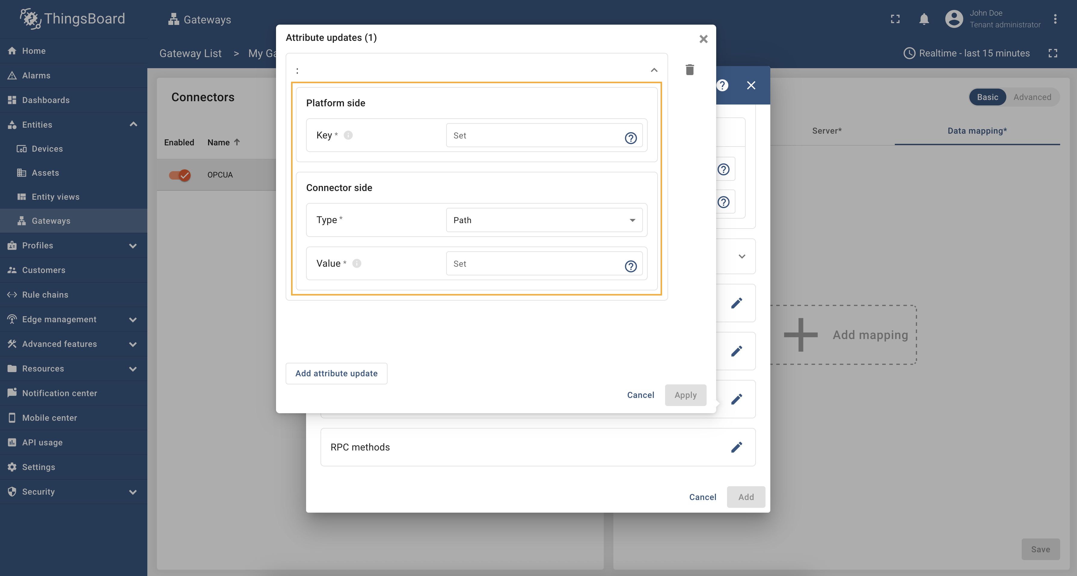
In order to add new attribute update, follow these steps:
-
Click the “pencil” icon in the “Attribute updates” section to add new attribute update;
-
Click on “Add attribute update” in the opened window;
-
Enter the “Key” field, select the “Type” (can be path, identifier or constant), enter “Value” and click “Apply” button.
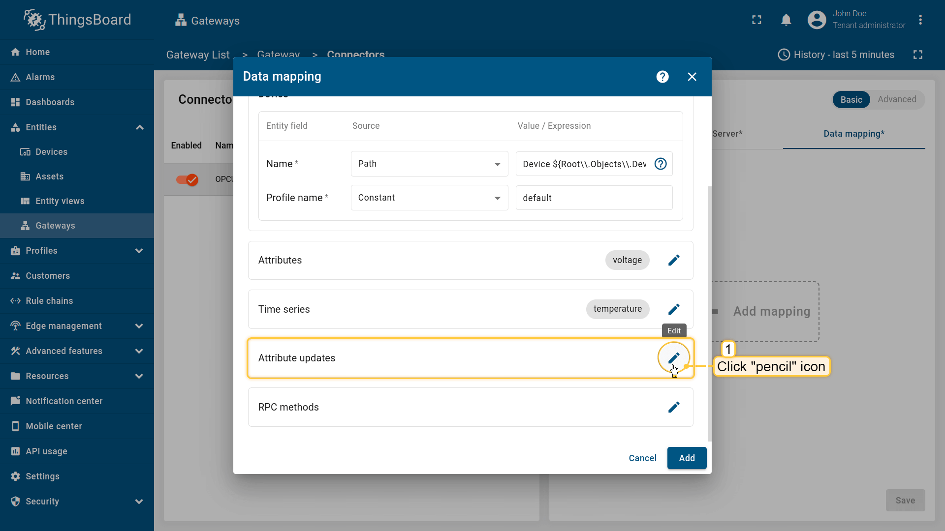
Click the “pencil” icon in the “Attribute updates” section to add new attribute update;
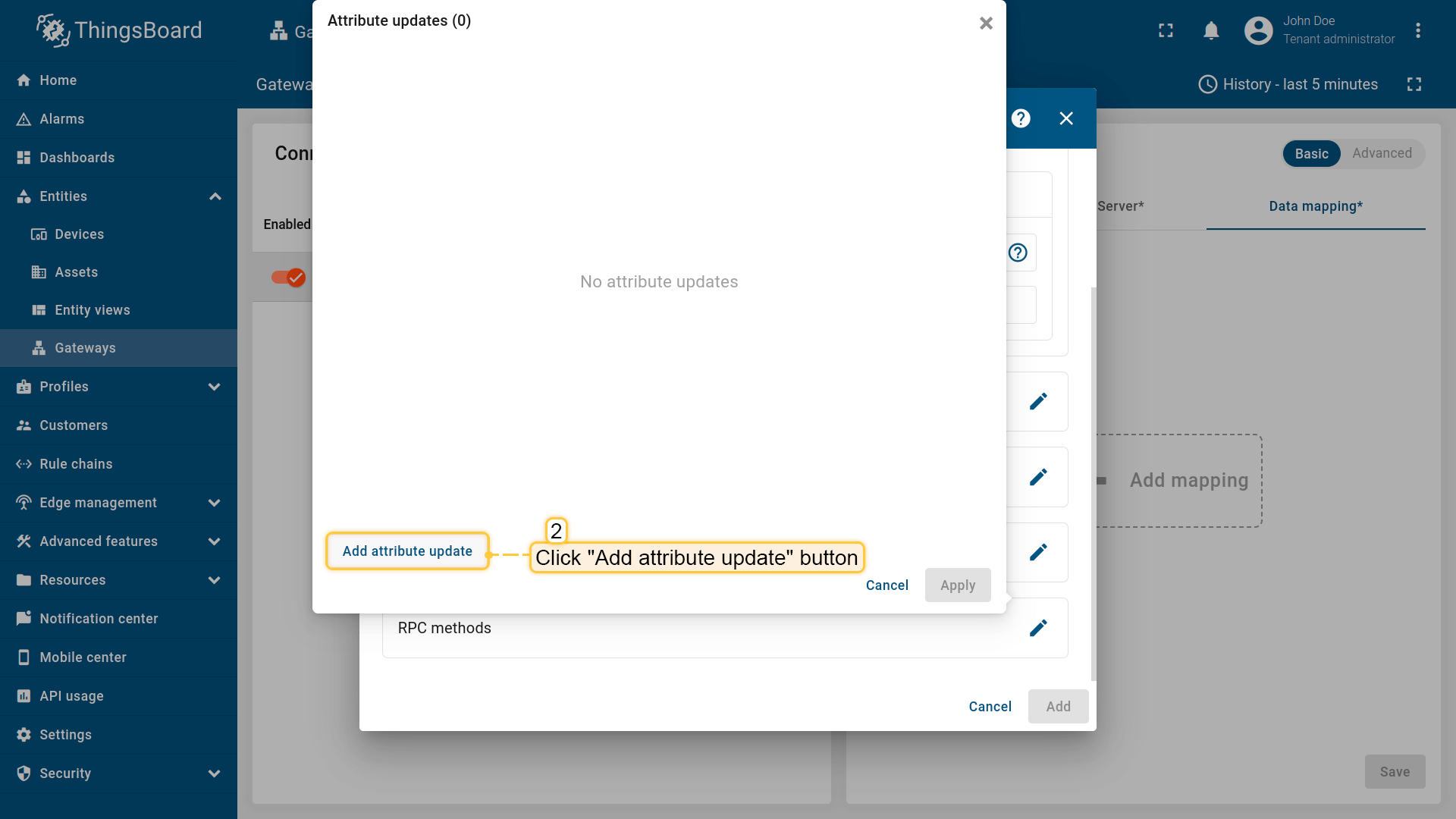
Click on “Add attribute update” in the opened window;
, [identifier](#identifier-types) or constant), enter "Value" and click "Apply" button.](/images/gateway/opc-ua-connector/opc-ua-gateway-configuring-13-ce.png)
Enter the “Key” field, select the “Type” (can be path, identifier or constant), enter “Value” and click “Apply” button.
Subsection “RPC methods”
ThingsBoard allows sending RPC commands to devices connected directly to ThingsBoard or via Gateway. The following parameters are used to configure RPC methods:
- Method name - the name of the method on OPC-UA server.
- Arguments - list of arguments that will pass to OPC-UA server method.
All configuration parameters list, and their detailed description can be found in the Advanced configuration section.
More usage examples can be found in the Usage examples section.
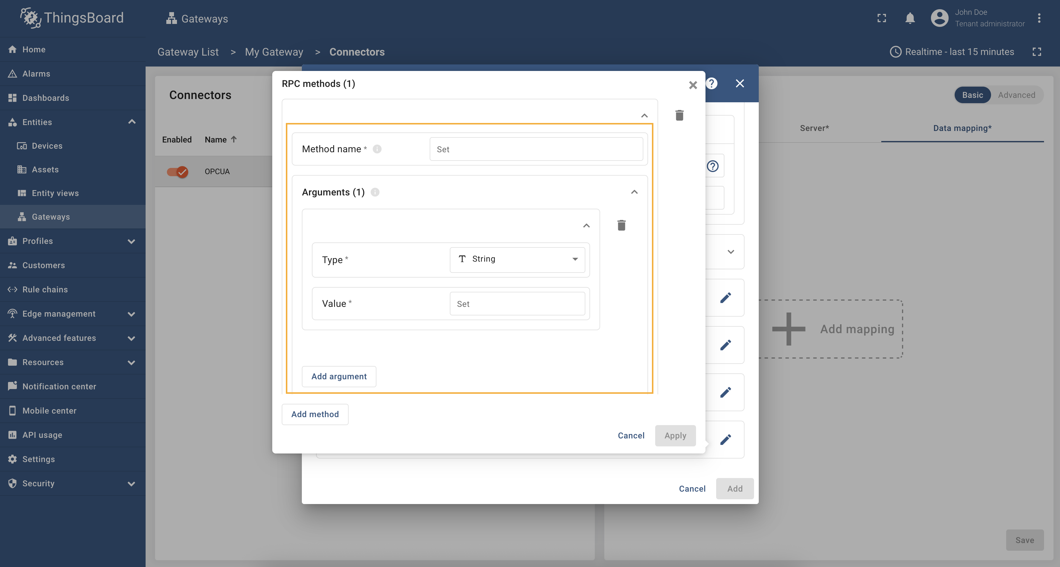
In order to add new RPC method, follow these steps:
-
Click the “pencil” icon in the “RPC methods” section to add new RPC method;
-
Click on “Add method” in the opened window;
-
Fill in “Method name” field. If the method has arguments, click on “Add argument” button and select the type of argument. Fill in the “Value” field and click “Apply” button.
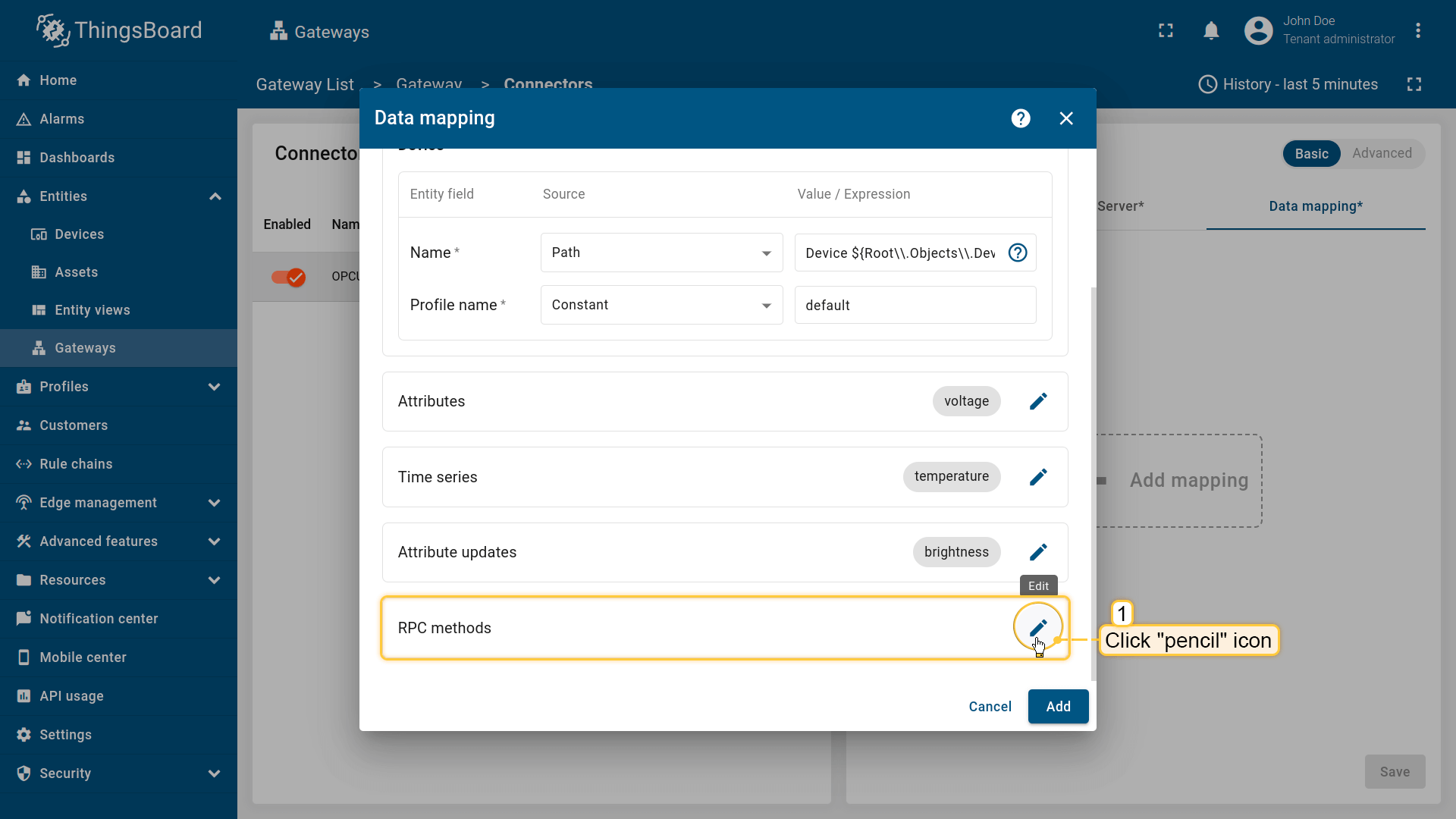
Click the “pencil” icon in the “RPC methods” section to add new RPC method;
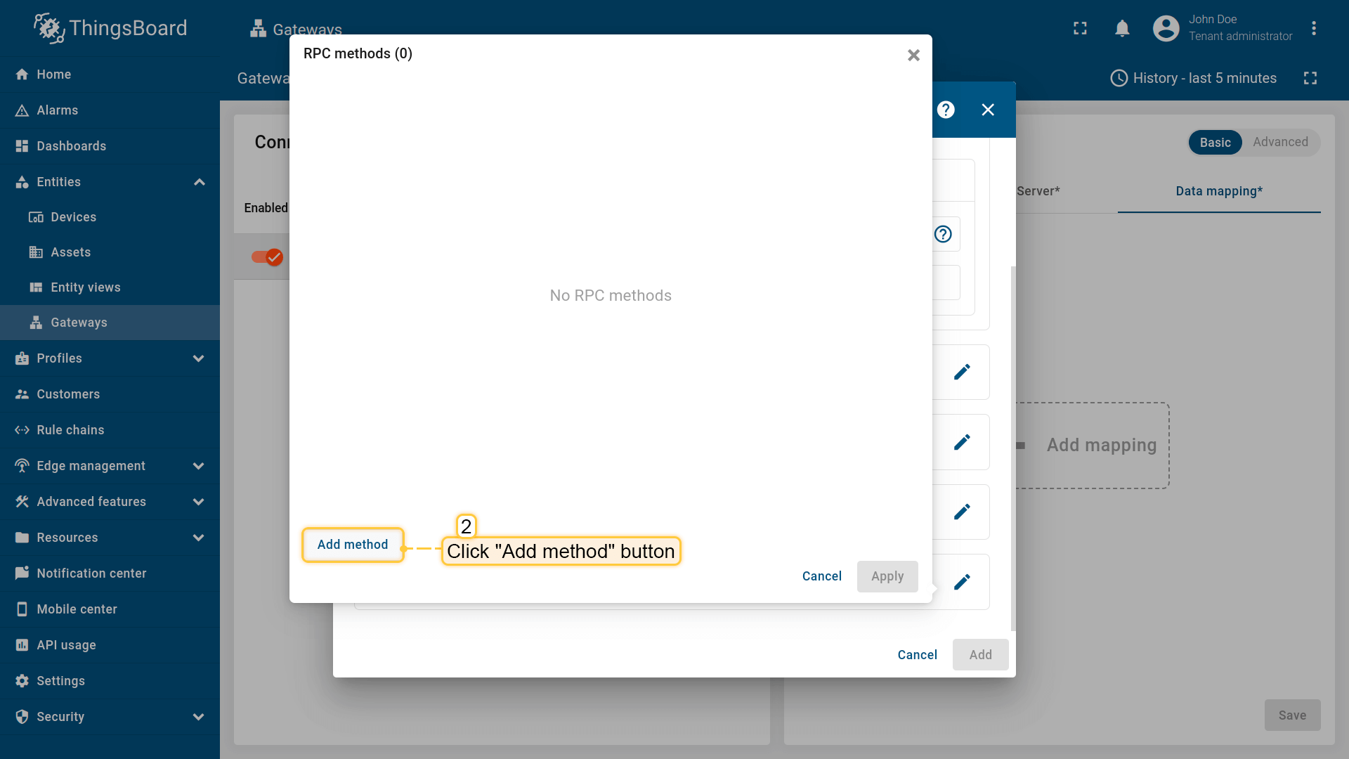
Click on “Add method” in the opened window;
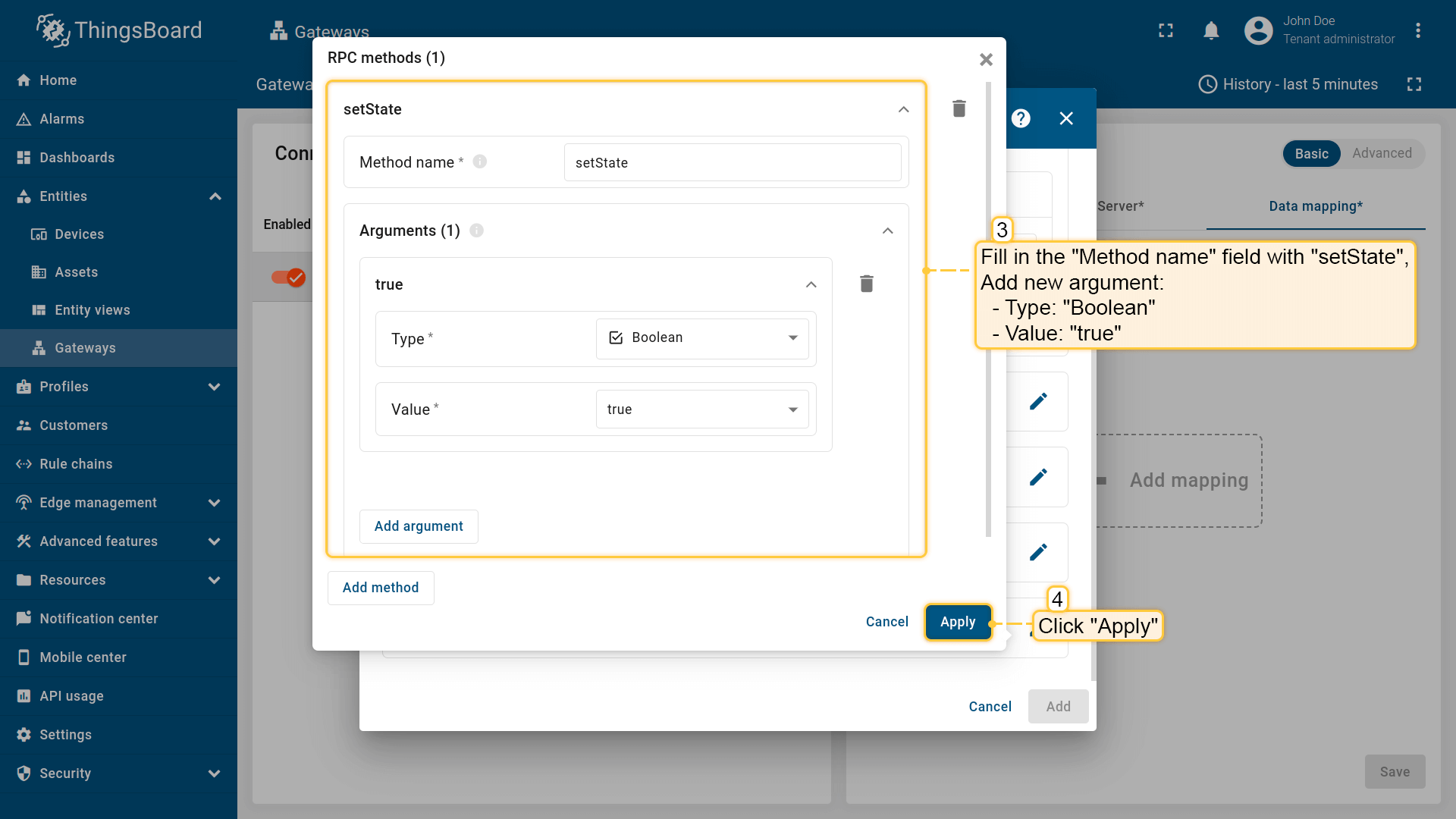
Fill in “Method name” field. If the method has arguments, click on “Add argument” button and select the type of argument. Fill in the “Value” field and click “Apply” button.
Also, every telemetry and attribute parameter has built-in GET and SET RPC methods out of the box, so you don’t need to configure it manually. See the guide.
Usage examples
Attribute updates allow you to update node values in the OPC-UA server. You can add new attribute updates in the “Attribute updates” section of the device configuration page. As an example, we will use Prosys OPC-UA Simulation Server, which is available at
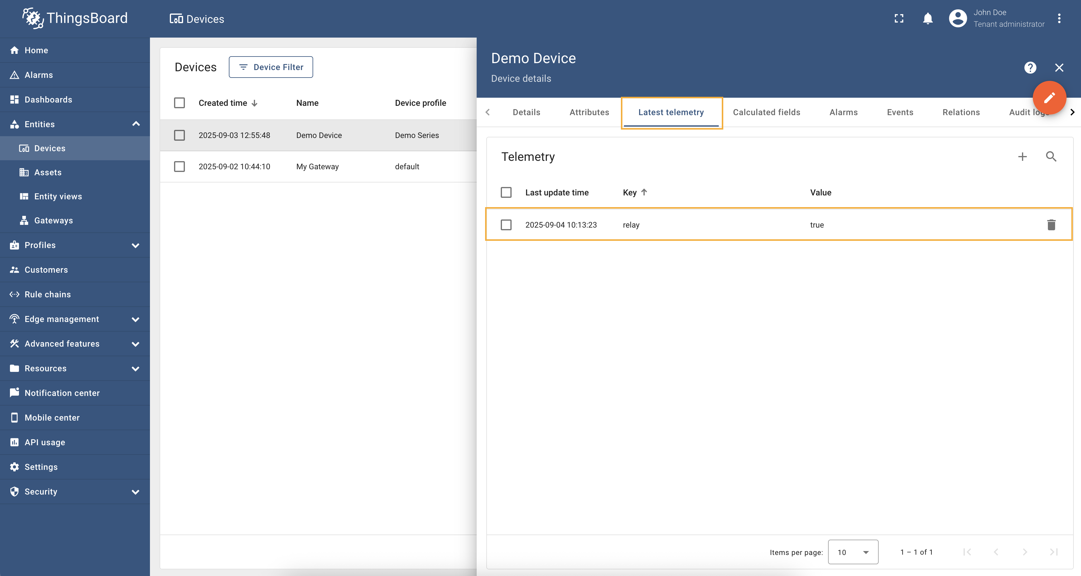
Example: Relay Controlling (Relative Path)We are interested in node “Relay”, we added this node as a telemetry parameter with the key Let’s add an attribute update to our configuration. For this purpose, follow these steps:
Go to “Entities” → “Gateways” in the right sidebar and select your gateway. Click on the “Connectors configuration” button on the right side menu. {:target="_blank"} guide or [Connection settings](/docs/iot-gateway/config/opc-ua/#connection-settings) and [Data mapping](/docs/iot-gateway/config/opc-ua/#data-mapping) sections of this guide). Click on the "Pencil" icon on a device you want to configure attribute updates for.](/images/gateway/opc-ua-connector/examples/attribute-updates-relative-path-1.png) Select the created OPC-UA connector, click on the “Data mapping” tab. Make sure you have configured and connected device (if you do not know how to do it, see Getting Started guide or Connection settings and Data mapping sections of this guide). Click on the “Pencil” icon on a device you want to configure attribute updates for. 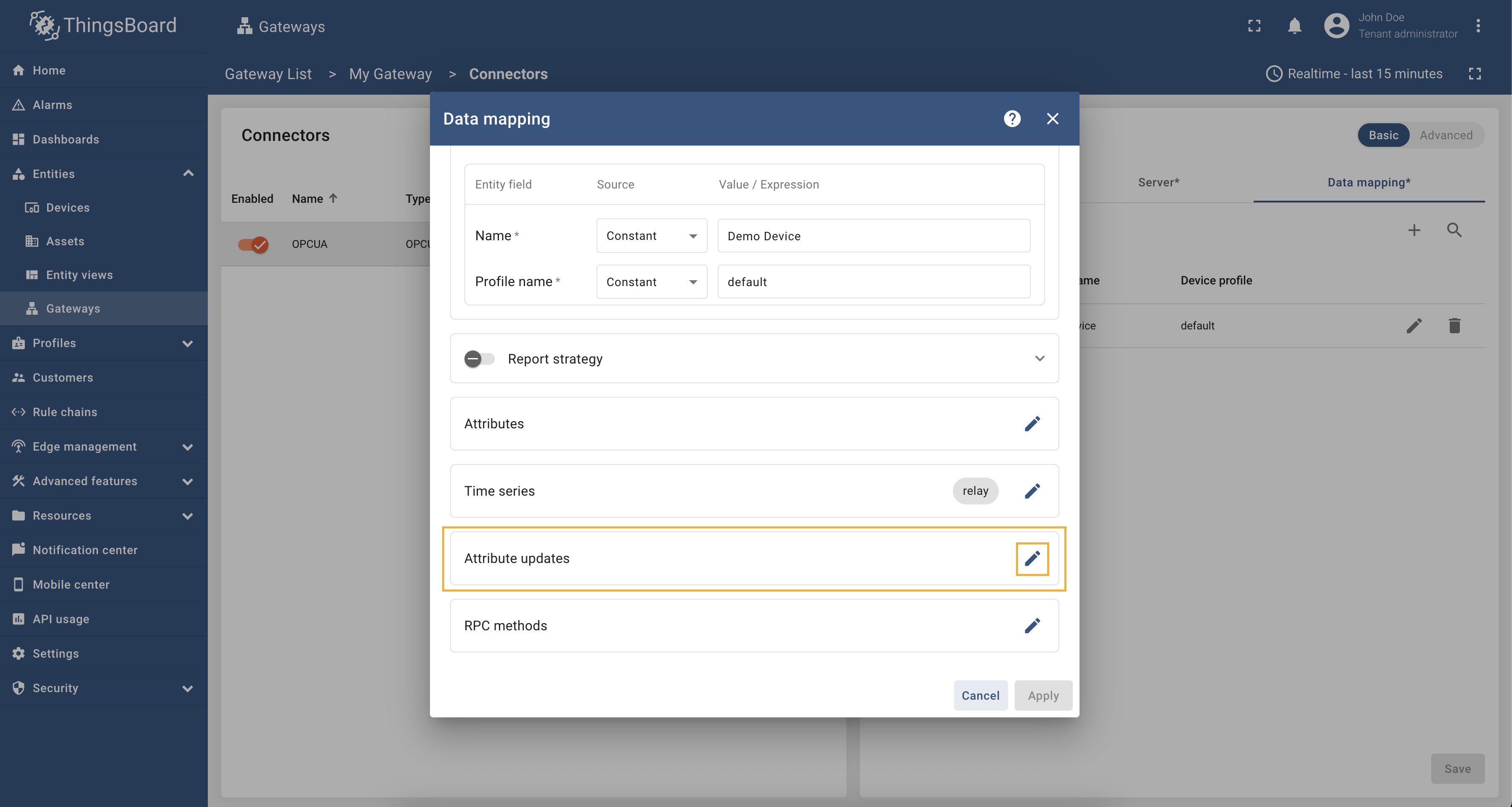 Scroll down to the “Attribute updates” section and click on the “Pencil” icon to edit the attribute updates.  Click on the “Add attribute update” button. In our case, we will add Remember to save your changes by clicking the “Apply” button. Now we can check if the attribute update works. Go to “Entities” → “Devices” → select a created device → “Attributes” tab →
select “Shared attributes” → click on the “+” icon and add 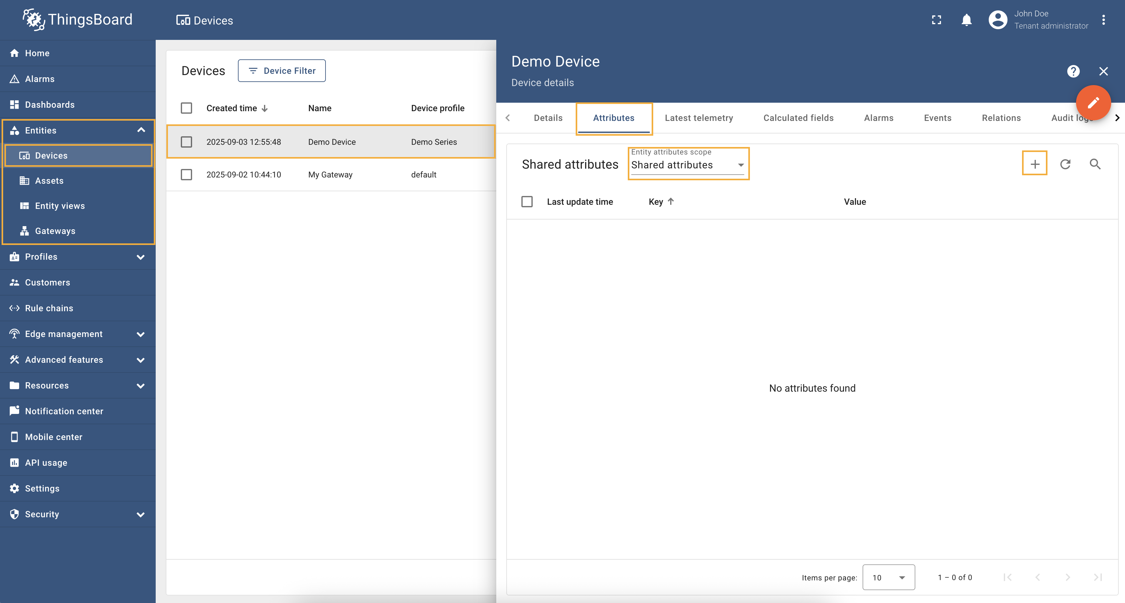 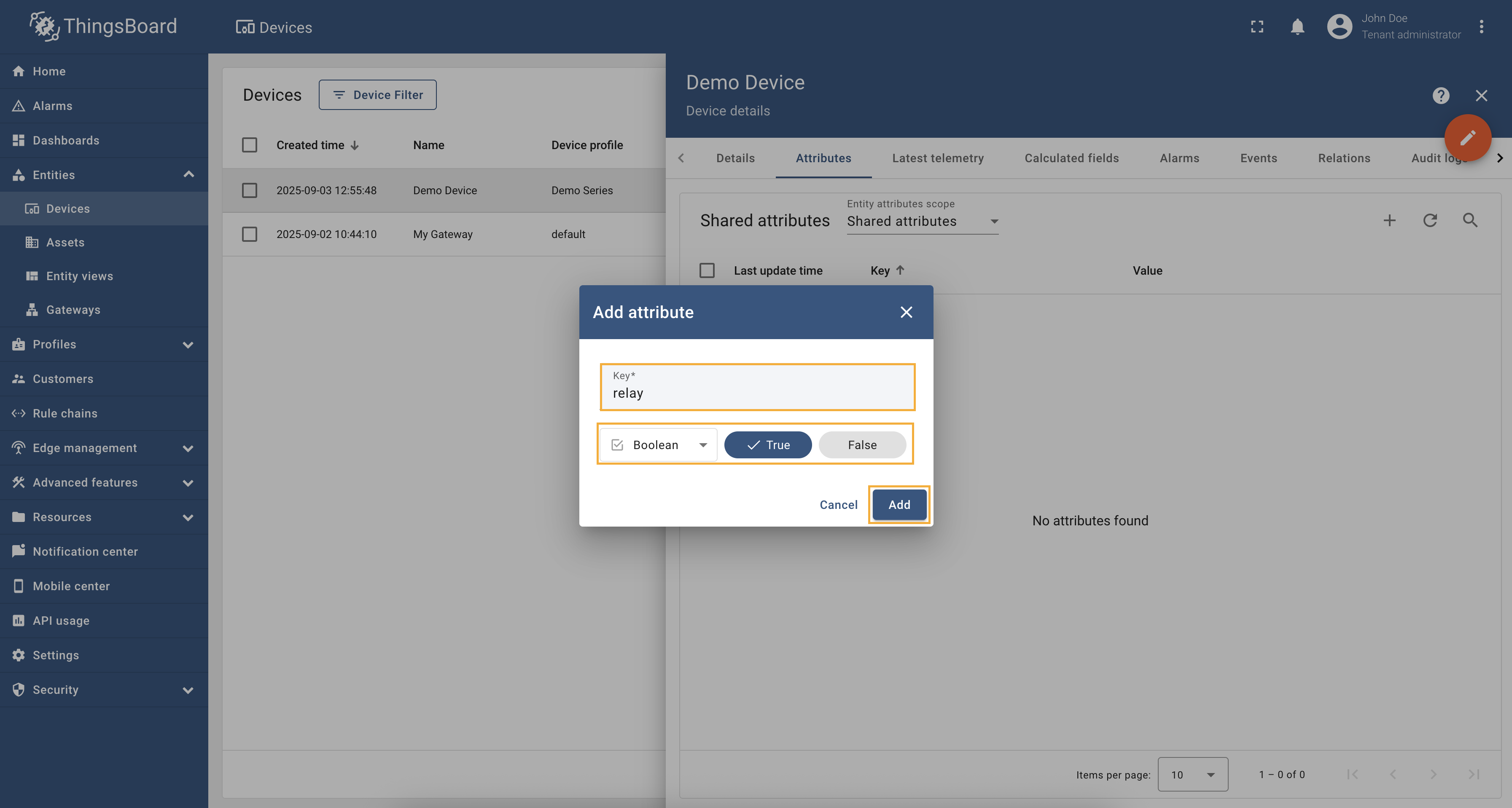 Now, let’s check the value of the relay node. In the selected device, go to the “Last telemetry” tab and check the
value of the
Try to change the value of the Full configuration for OPC-UA connector for the examples above will look like this: |
Attribute updates allow you to update node values in the OPC-UA server. You can add new attribute updates in the “Attribute updates” section of the device configuration page. As an example, we will use Prosys OPC-UA Simulation Server, which is available at
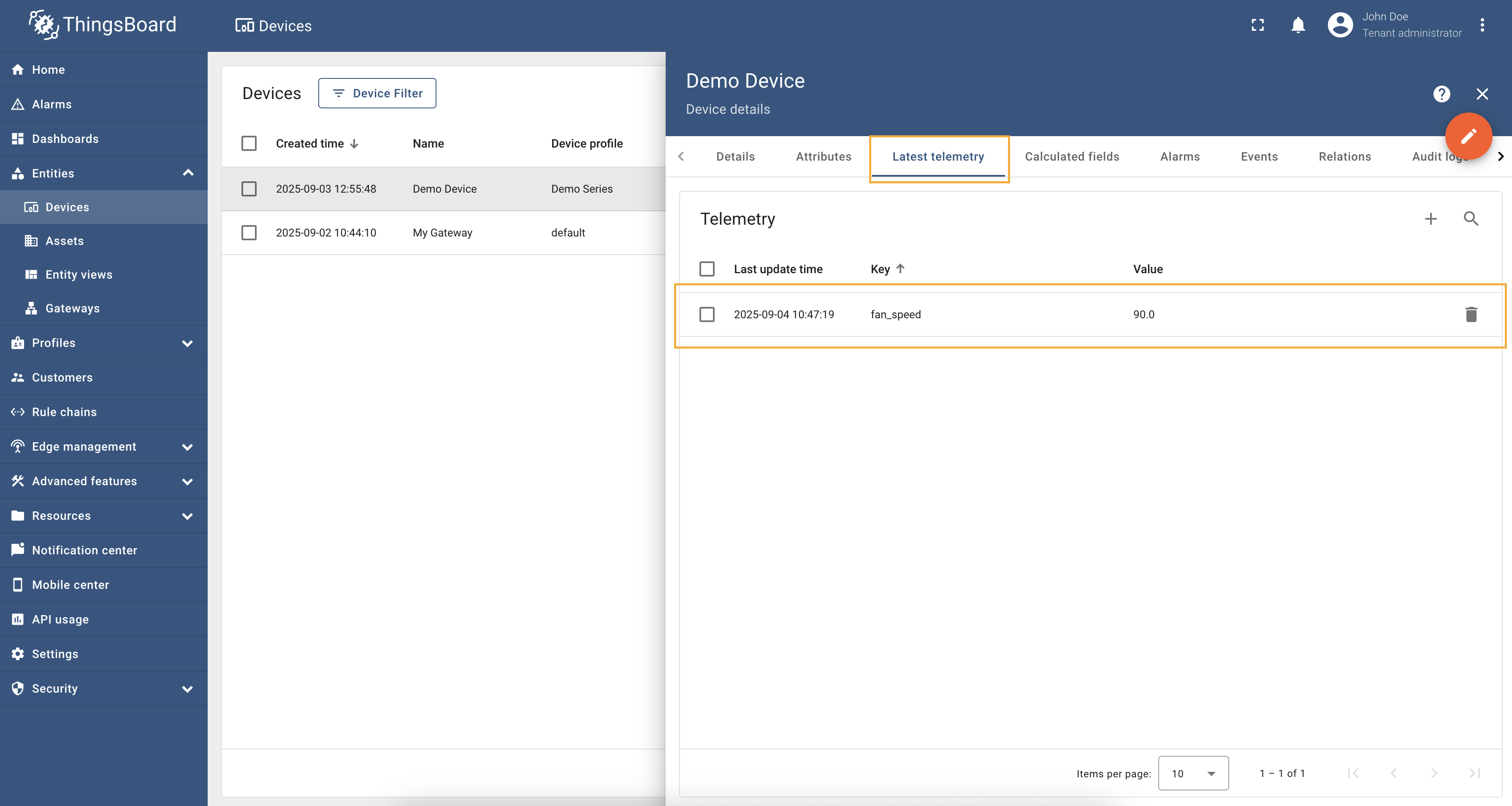
Example: Fan Speed (Absolute Path)We are interested in node “FanSpeed”, we added this node as a telemetry parameter with the key Let’s add an attribute update to our configuration. For this purpose, follow these steps:
Go to “Entities” → “Gateways” in the left sidebar and select your gateway. Click on the “Connectors configuration” button on the right side menu. Select the created OPC-UA connector, click on the “Data mapping” tab. Make sure you have configured and connected device (if you do not know how to do it, see Getting Started guide or Connection settings and Data mapping sections of this guide). Click on the “Pencil” icon on a device you want to configure attribute updates for.  Scroll down to the “Attribute updates” section and click on the “Pencil” icon to edit the attribute updates. 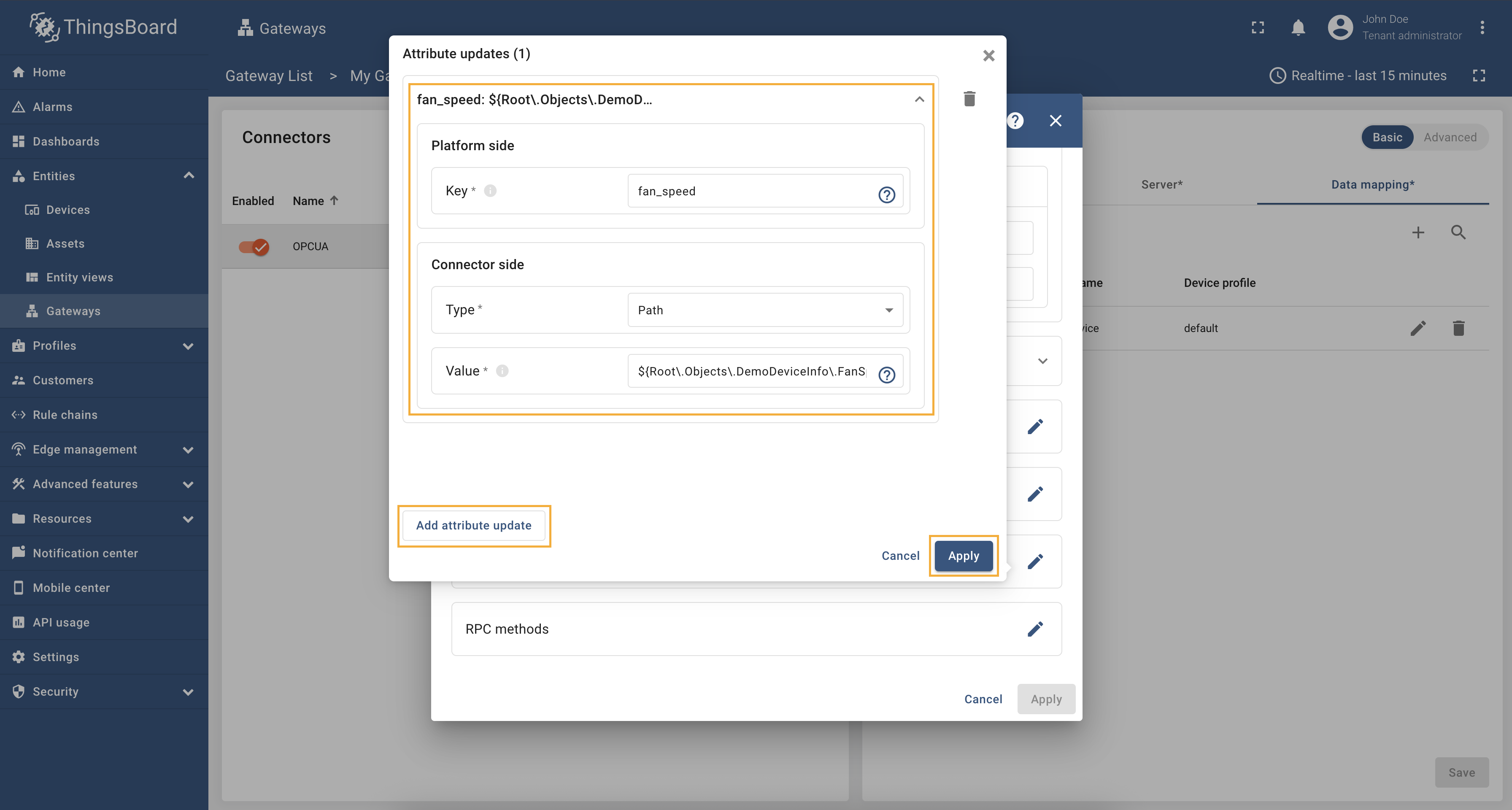 Click on the “Add attribute update” button. In our case, we will add Remember to save your changes by clicking the “Apply” button. Now we can check if the attribute update works. Go to “Devices” → select a created device → “Attributes” tab →
select “Shared attributes” → click on the “+” icon and add 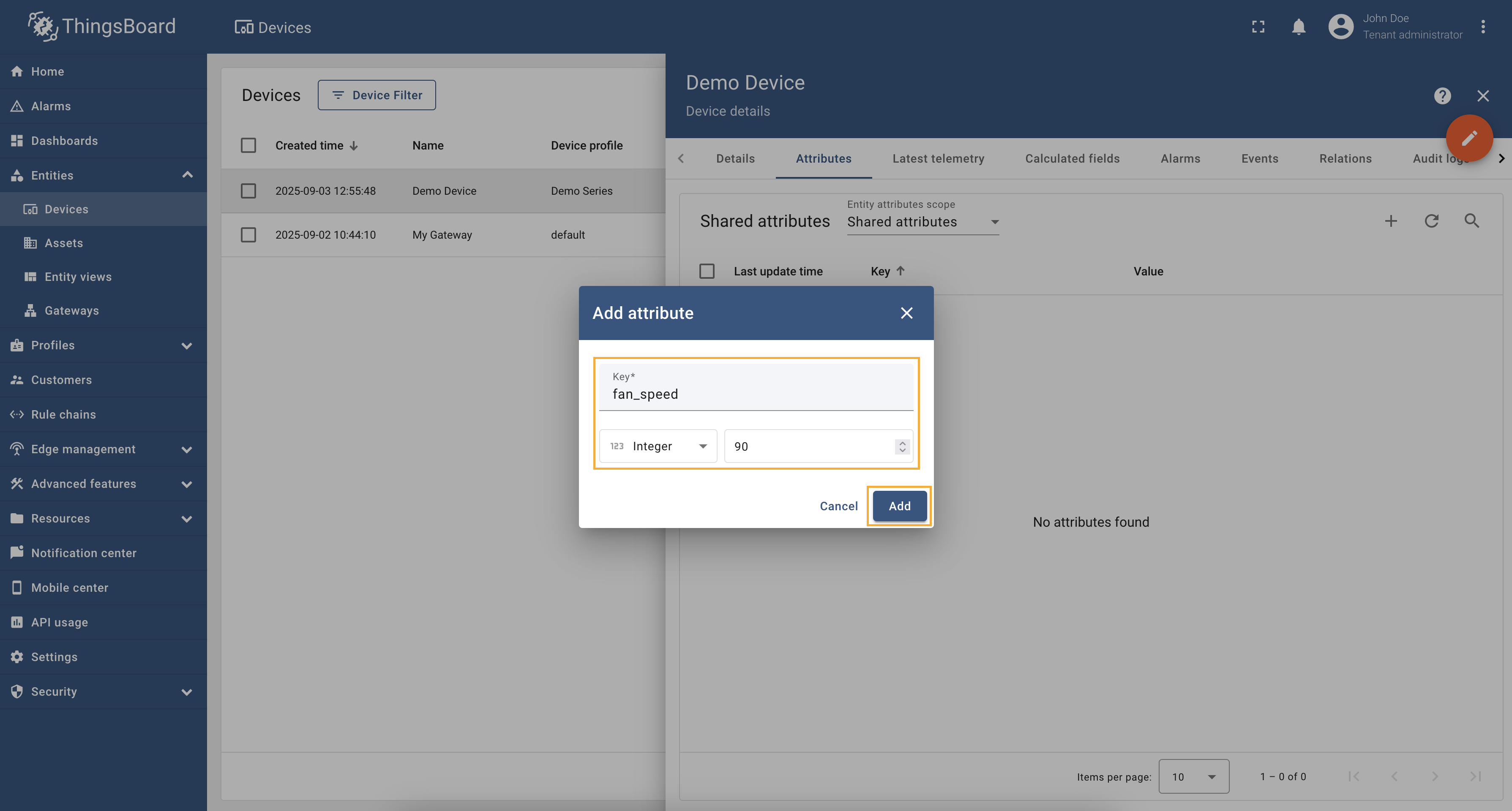 Now, let’s check the value of the fan speed node. In the selected device, go to the “Last telemetry” tab and check the
value of the
Try to change the value of the Full configuration for OPC-UA connector for the examples above will look like this: |
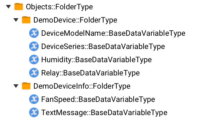
Attribute updates allow you to update node values in the OPC-UA server. You can add new attribute updates in the “Attribute updates” section of the device configuration page. As an example, we will use Prosys OPC-UA Simulation Server, which is available at
Example: Text Message Editing (Identifier)We are interested in node “TextMessage”, we added this node as a telemetry parameter with the key Let’s add an attribute update to our configuration. For this purpose, follow these steps:
Go to “Entities” → “Gateways” in the right sidebar and select your gateway. Click on the “Connectors configuration” button on the right side menu. Select the created OPC-UA connector, click on the “Data mapping” tab. Make sure you have configured and connected device (if you do not know how to do it, see Getting Started guide or Connection settings and Data mapping sections of this guide). Click on the “Pencil” icon on a device you want to configure attribute updates for. 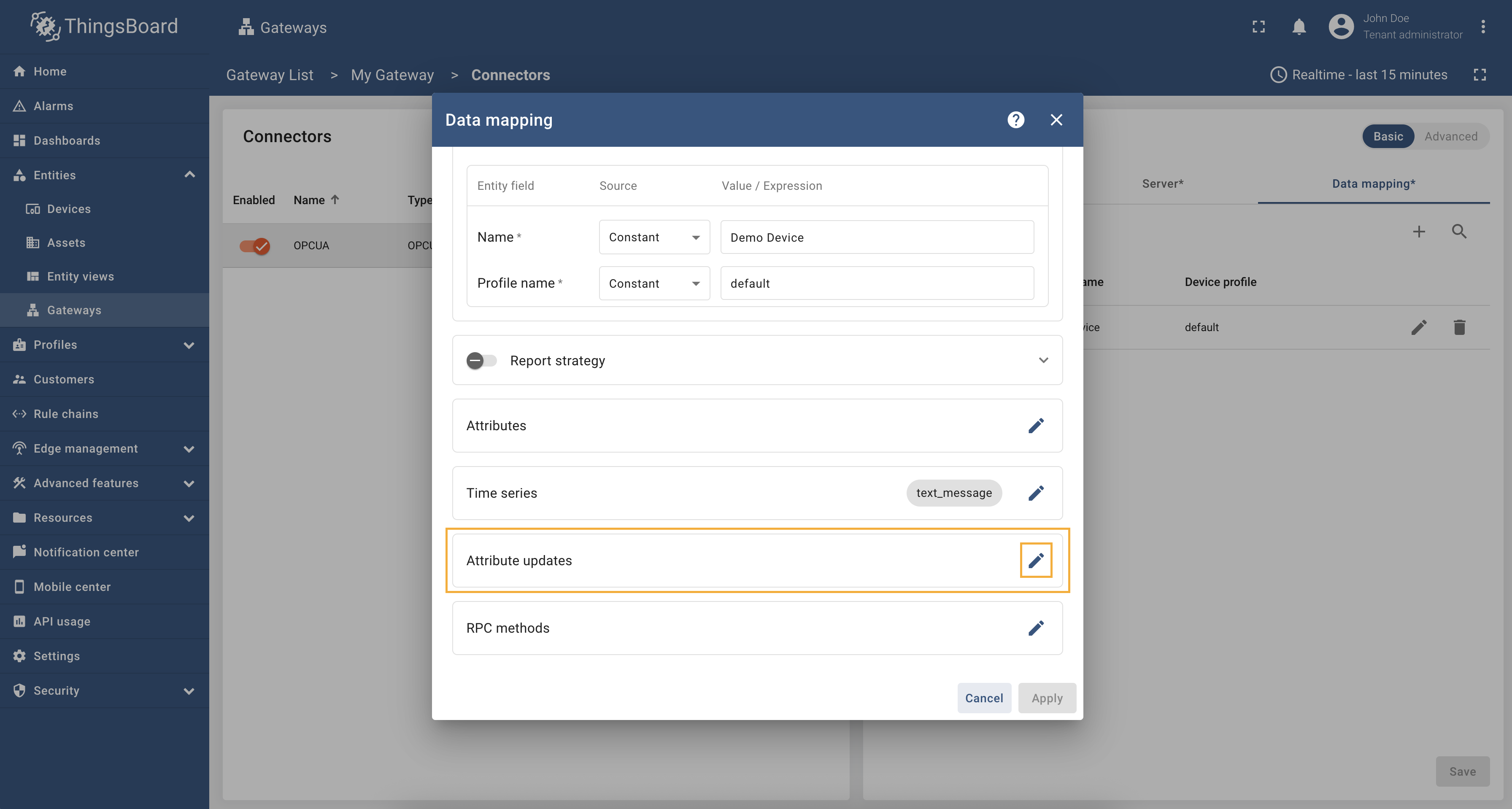 Scroll down to the “Attribute updates” section and click on the “Pencil” icon to edit the attribute updates.  Click on the “Add attribute update” button. In our case, we will add Remember to save your changes by clicking the “Apply” button. Now we can check if the attribute update works. Go to “Devices” → select a created device → “Attributes” tab →
select “Shared attributes” → click on the “+” icon and add  Now, let’s check the value of the text message node. In the selected device, go to the “Last telemetry” tab and check the
value of the
Try to change the value of the Full configuration for OPC-UA connector for the examples above will look like this: |

RPC to Device allows you to execute an OPC-UA server method on a specific device. It is important to note that the method you are calling must be defined on the OPC-UA server. As an example, we will use ThingsBoard OPC-UA Demo Server, which can be run using Docker and the following command: The server has the following endpoint URL: Example: Multiplying NumbersWe are interested in “multiply” method node which will multiply two numbers that we will pass as arguments. To call this method, first we need to configure the OPC-UA connector to support RPC calls. For this purpose, follow these steps:
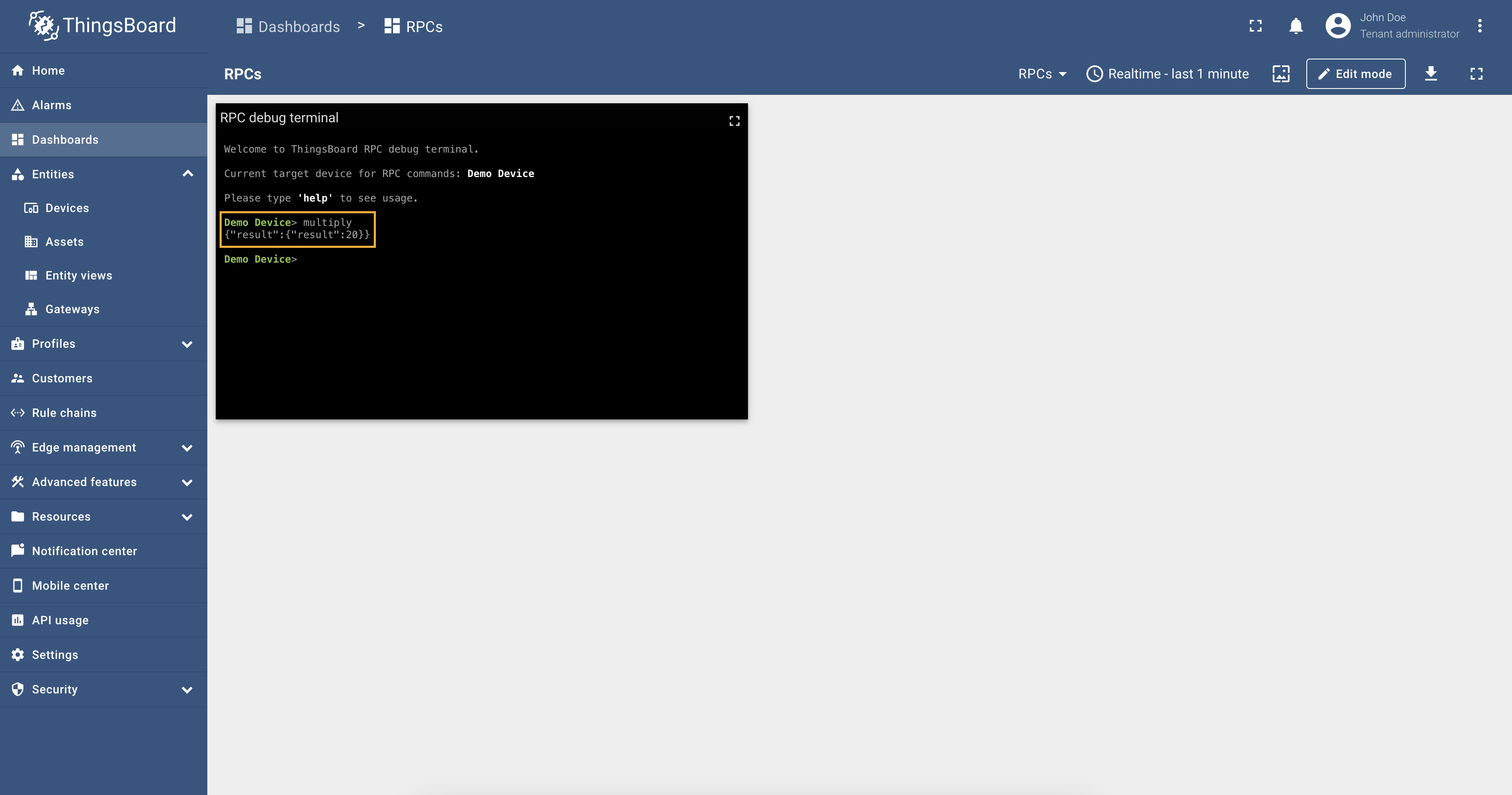
Go to “Entities” → “Gateways” in the right sidebar and select your gateway. Click on the “Connectors configuration” button on the right side menu. Select the created OPC-UA connector, click on the “Data mapping” tab. Make sure you have configured and connected device (if you do not know how to do it, see Getting Started guide or Connection settings and Data mapping sections of this guide). Click on the “Pencil” icon on a device you want to configure RPC method for. 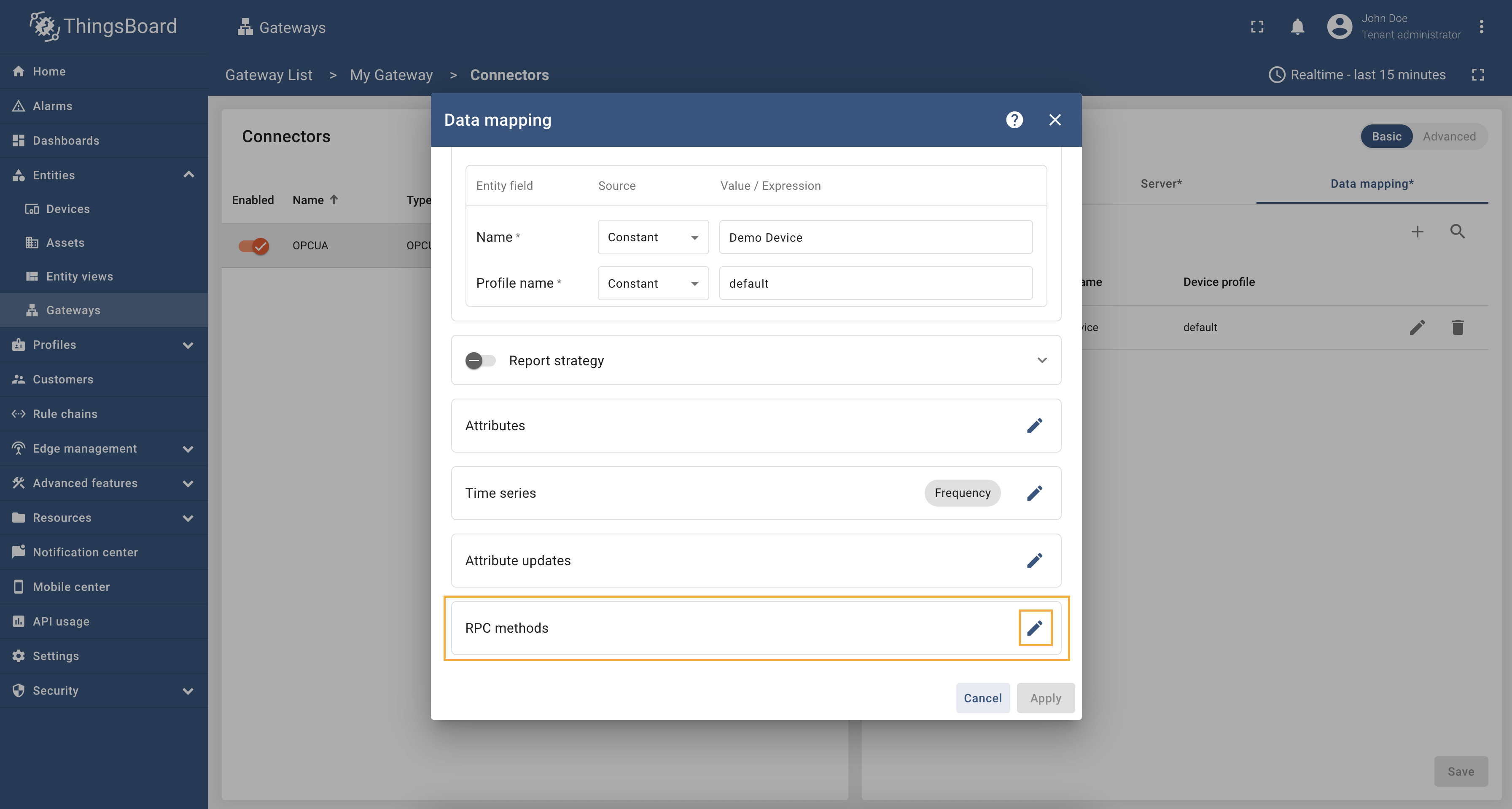 Scroll down to the “RPC methods” section and click on the “Pencil” icon to edit the RPC methods. 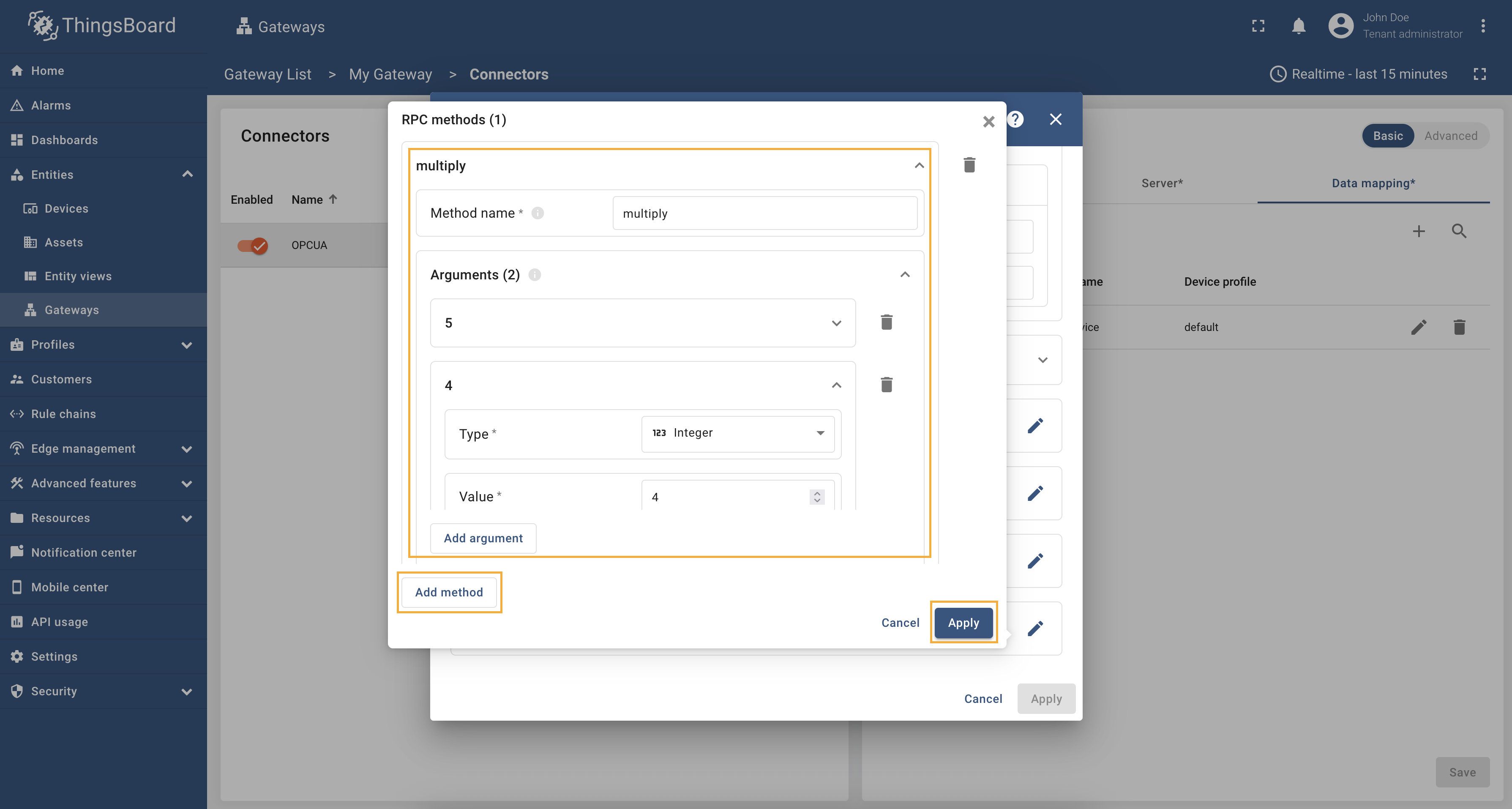 Click on the “Add method” button. In our case, we will add the Remember to save your changes by clicking the “Apply” button. We are done with configuration, so let’s check how to call the method. In the RPC Debug Terminal widget, run the following command: In this case, the method will be called with the arguments that we specified in the configuration (default arguments). As you remember, in our case, we enter 5 and 4, so the result is:
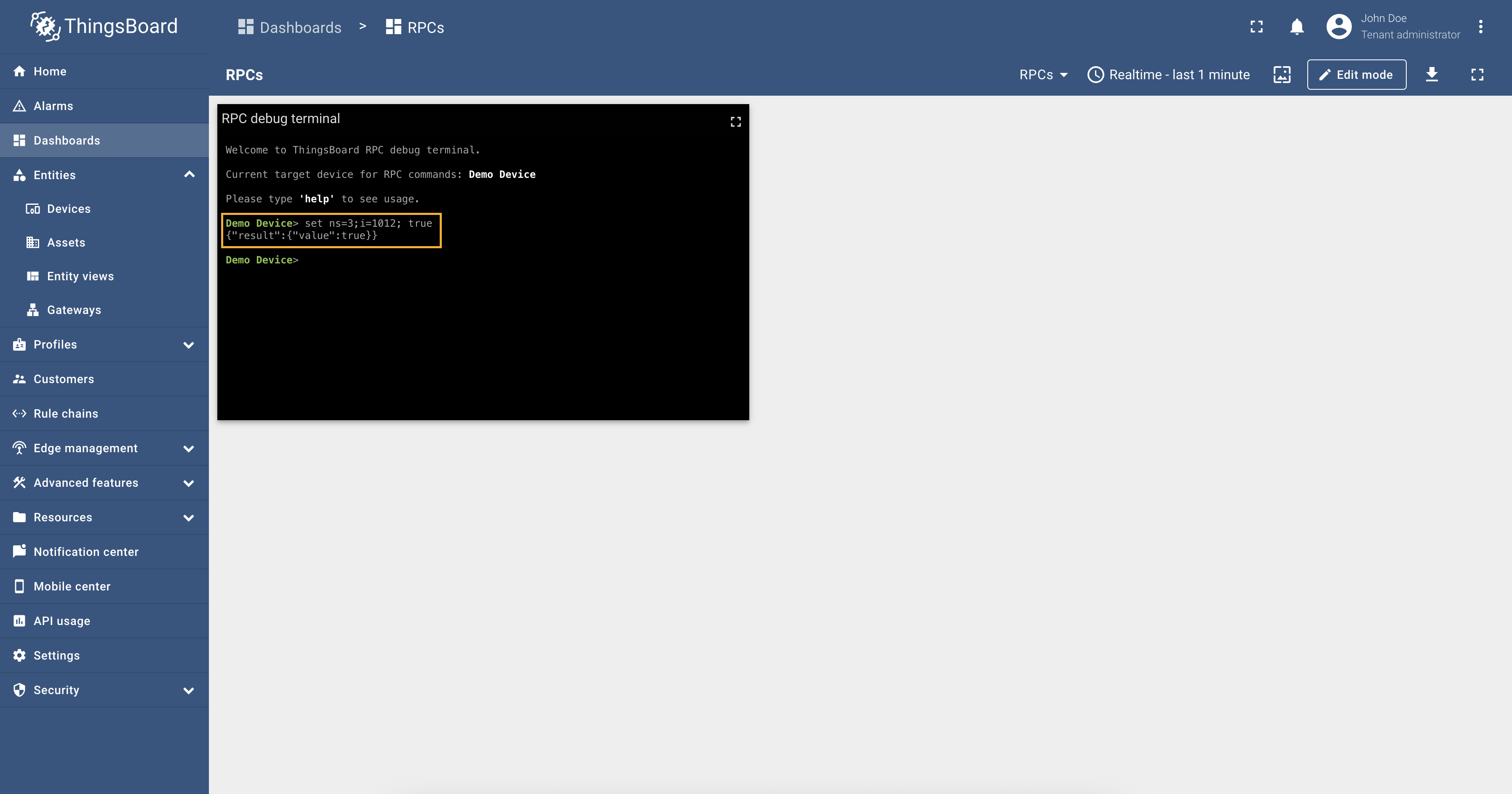
Also, we can pass arguments to the method directly from the RPC Debug Terminal widget using the following command: Response:
Full configuration for OPC-UA connector for the example above will look like this: |

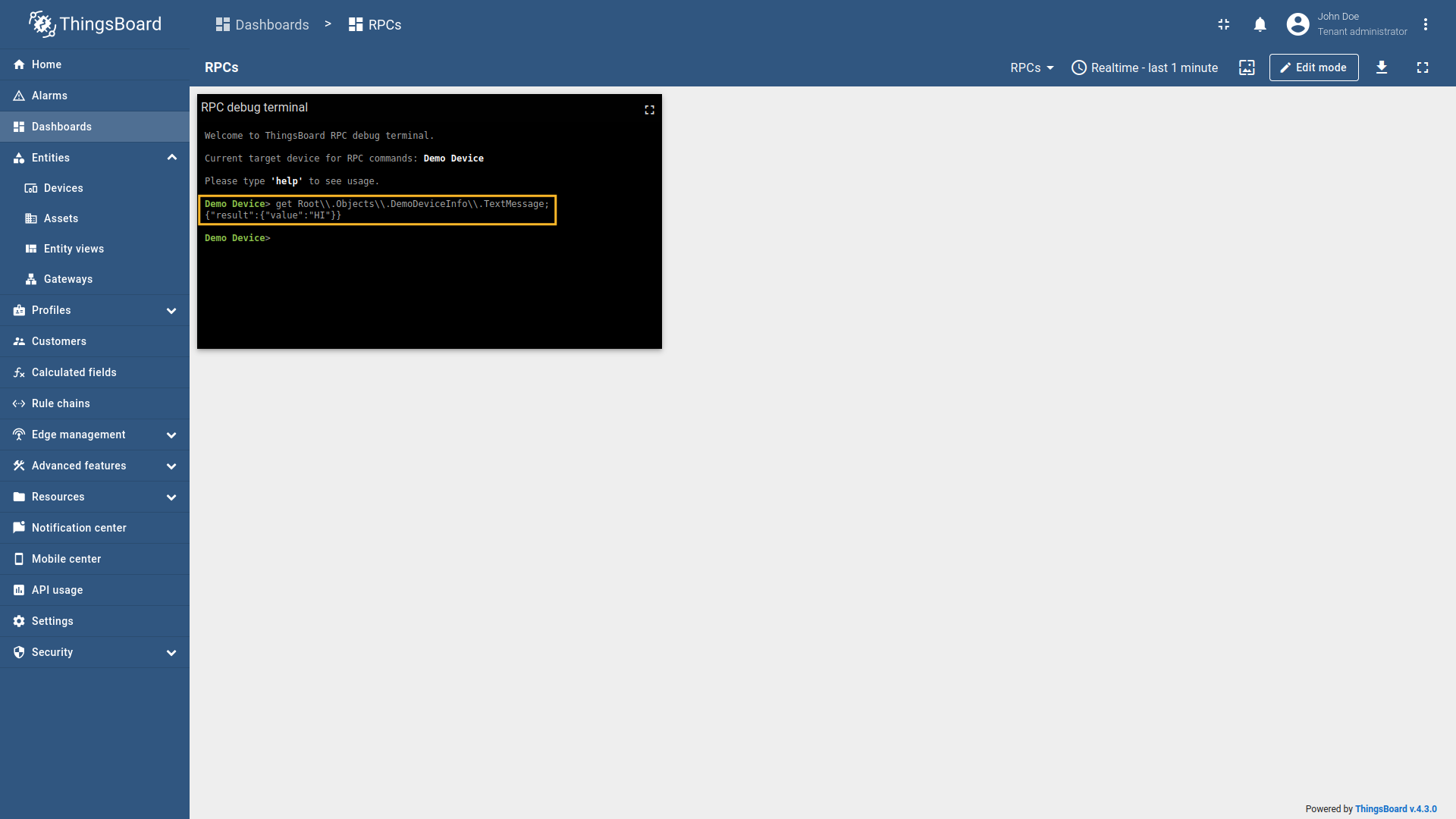
Every telemetry and attribute parameter has As an example, we will use Prosys OPC-UA Simulation Server, which is
available at
We are interested in node “Relay” that have Let’s check the value of the relay node using the reserved Response:
So, the The RPC Debug Terminal is used only for example purpose, so you can use any other widget that supports RPC calls. To set the value of the relay node and turn it on, run the query: Response: And as you can see, from the screenshot below, the relay telemetry value has changed to
Also, let’s check the value of the relay telemetry again: Response:
Full configuration for OPC-UA connector for the examples above will look like this: |


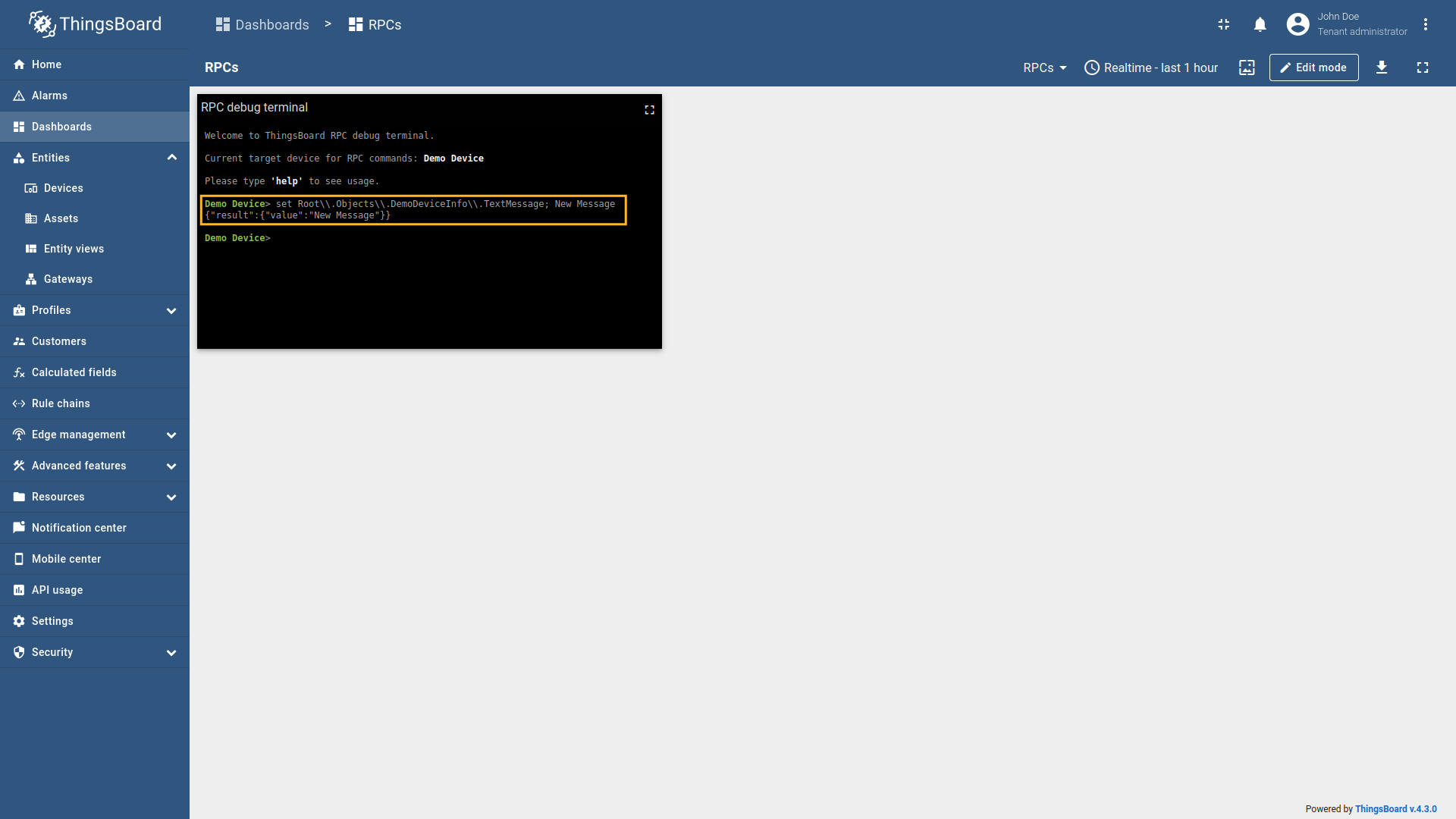
Every telemetry and attribute parameter comes with built-in Additionally, you can use the reserved RPC methods to access any node on the OPC-UA server - even if it doesn’t belong to a specific device. This is especially useful when management or control nodes are located outside the device’s node tree.
We will set the device node to
We’re interested in the “TextMessage” which has the “Path” - Let’s check the value of the textmessage node using the reserved Response:
So, the The RPC Debug Terminal is used only for example purpose, so you can use any other widget that supports RPC calls. To set the value of the textmessage node and change its value, run the query: Response: And as you can see, from the screenshot below, the textmessage telemetry value has changed to
Also, let’s check the value of the textmessage telemetry again: Response:
Full configuration for OPC-UA connector for the examples above will look like this: |

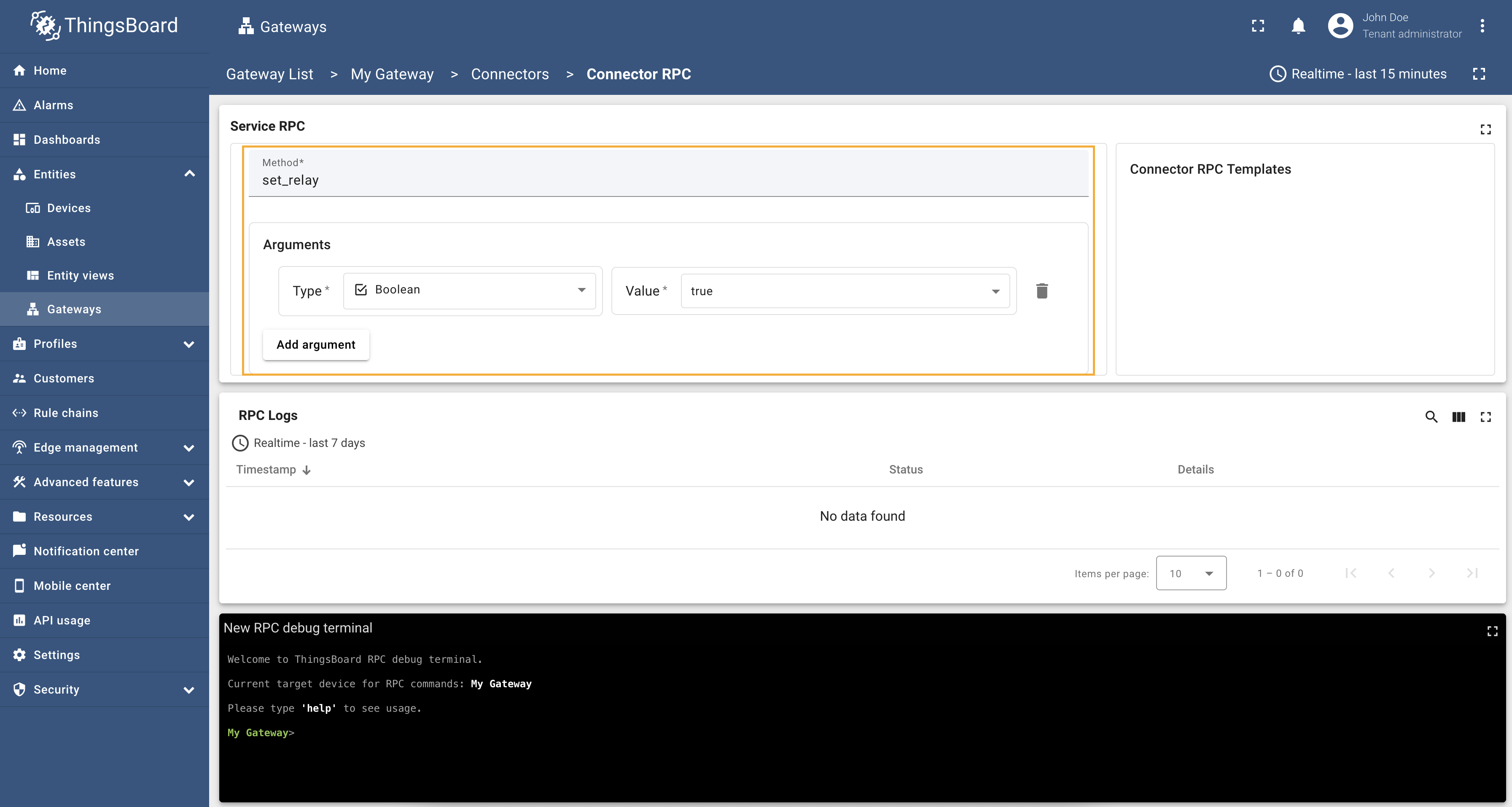
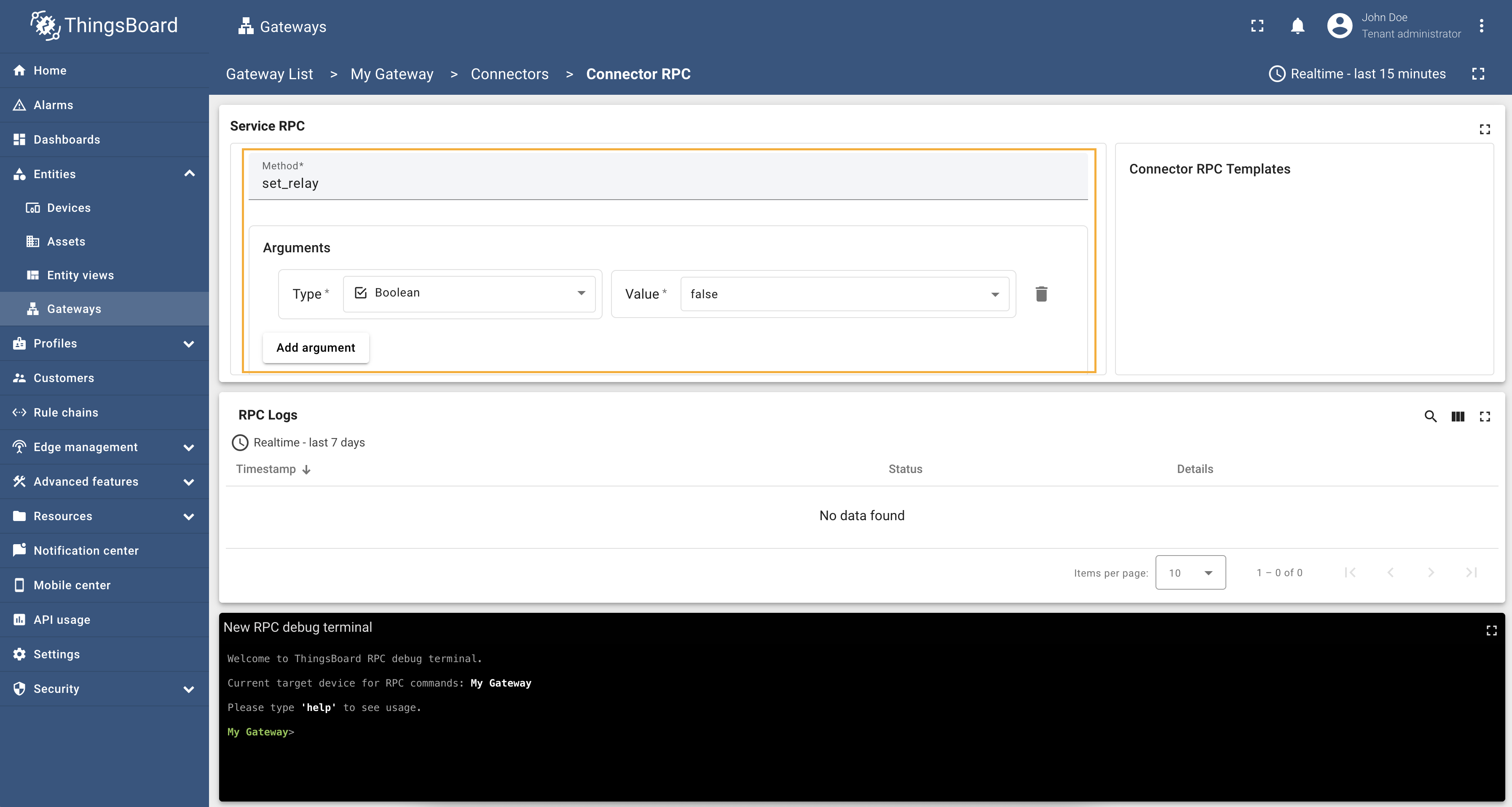
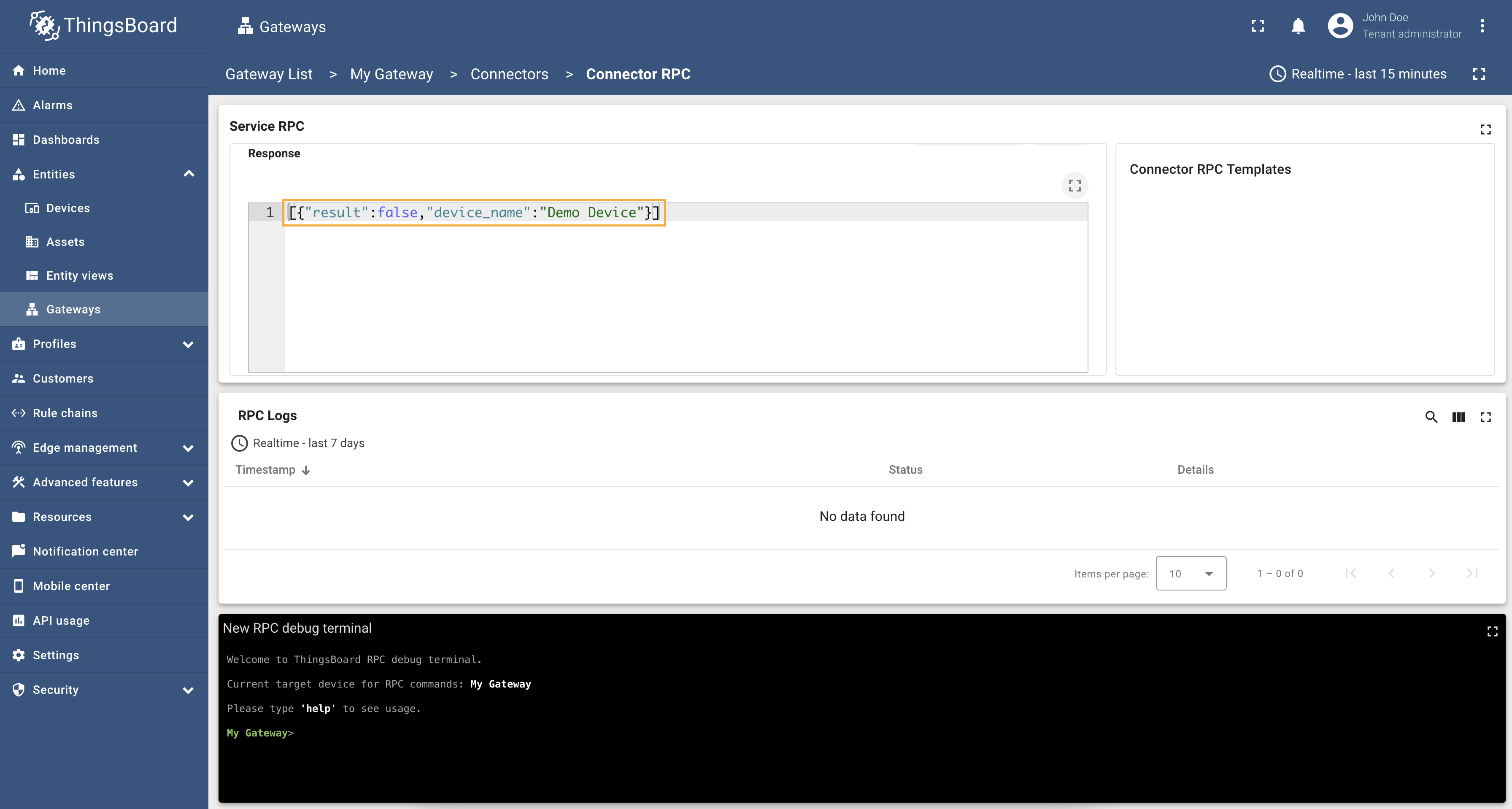
RPC To Connector allows you to send a command to the connector from the ThingsBoard IoT Gateway UI. It is important to note that the method you are calling must be defined on the OPC-UA server. Please note: The RPC To Connector will execute the method on every device that has the OPC-UA connector configured. As an example, we will use ThingsBoard OPC-UA Demo Server, which can be run using Docker and the following command: The server has the following endpoint URL: Example: Relay ControllingLet’s see a practical example of using RPC To Connector. On our OPC-UA server, we have “set_relay” method that
turns on or off the relay. The method accepts a boolean argument, where
Go to “Entities” → “Gateways” in the right sidebar and select your gateway. Click on the “Connectors configuration” button on the right side menu. {:target="_blank"} guide or [Connection settings](/docs/iot-gateway/config/opc-ua/#connection-settings) and [Data mapping](/docs/iot-gateway/config/opc-ua/#data-mapping) sections of this guide).](/images/gateway/opc-ua-connector/examples/rpc-to-connector-1.png) Select the created OPC-UA connector, click on the “RPC” icon. Make sure you have configured and connected device (if you do not know how to do it, see Getting Started guide or Connection settings and Data mapping sections of this guide). Let’s first turn on the relay. To do this, fill in the “Method” field with
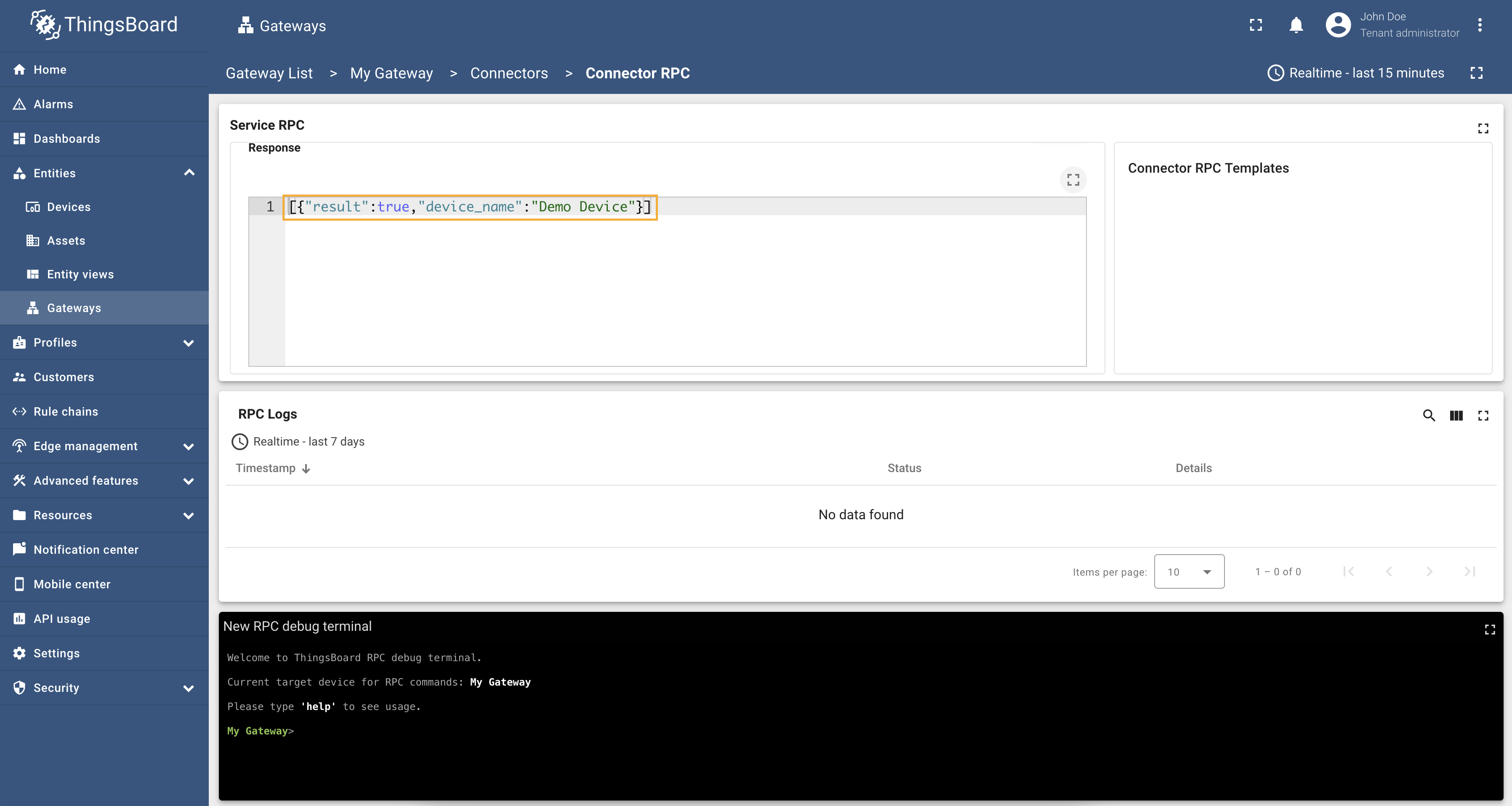
As you can see, the response contains
And finally, let’s turn off the relay. To do this, fill in the “Method” field with
Result:
Full configuration for OPC-UA connector for the example above will look like this: |
Advanced configuration
The advanced configuration section provides a detailed overview of all available parameters for the OPC-UA connector.
Server
The server object specifies the target OPC-UA server and how the gateway interacts with it.
| Parameter | Default value | Description |
|---|---|---|
| server | The server object specifies the target OPC-UA server and how the gateway interacts with it. | |
| server.url | Hostname or ip address of OPC-UA server. | |
| server.timeoutInMillis (in ms) | 5000 | Timeout in seconds for connecting to OPC-UA server. |
| server.scanPeriodInMillis (in ms) | 3600000 | Period in milliseconds for scanning the OPC-UA server for changes. If your OPC-UA server structure doesn’t change often, you can set a big period for gateway resource saving. |
| server.pollPeriodInMillis (in ms) | 5000 | Period in milliseconds to poll the server. If enableSubscriptions is set to true, pollPeriodInMillis does not affect data reading. |
| server.enableSubscriptions | true | If true - the gateway will subscribe to interesting nodes and wait for data update and if false - the gateway will rescan OPC-UA server every scanPeriodInMillis. |
| server.subCheckPeriodInMillis (in ms) | 100 | Defines the publishing/check interval that the connector requests when creating OPC-UA subscriptions. |
| server.subKeepAlivePeriodInSeconds (in seconds) ** | 0 | The interval at which the connector checks whether OPC-UA subscriptions are still “alive” (i.e., the publish/data-change flow is not stalled). This check is disabled by default (set to 0). If a subscription shows no activity longer than this threshold, the connector treats it as expired and triggers resubscription to restore updates. |
| server.subDataMaxBatchSize | 1000 | Maximum number of data items in a single subscription update. This is useful for performance optimization. |
| server.subDataMinBatchCreationTimeMs (in ms) | 200 | Minimum time in milliseconds to wait before creating a new batch of data items in a subscription update. This helps to reduce the number of updates sent to ThingsBoard. |
| server.subscriptionProcessBatchSize | 2000 | Maximum number of data items to process in a single batch when handling subscription updates. This is useful for performance optimization. |
| server.sessionTimeoutInMillis (in ms) | 120000 | Session timeout in milliseconds. This is the maximum time the session can be inactive before it is closed by the server. |
| server.showMap | false | If true - the gateway will show a map of OPC-UA server nodes in the terminal. This is useful for debugging and understanding the structure of the OPC-UA server. |
| server.security | Basic128Rsa15 | Security policy (Basic128Rsa15, Basic256, Basic256Sha256). |
Please note: ** – Subscription lifetime in OPC-UA is negotiated using the publishing interval, keep-alive, and lifetime settings, and can be approximated as RequestedLifetimeCount * RequestedPublishingInterval. In asyncua, RequestedLifetimeCount is typically an internal default which is 1000 ms, while the publishing interval comes from the value used to create the subscription (here: server.subCheckPeriodInMillis, e.g. 100 ms), so the approximate lifetime is (1000 * 100) / 1000 = 100 seconds. However, the exact removal time depends on the OPC-UA server implementation and its cleanup logic - some servers keep subscriptions longer, others may drop them earlier under load or session/publish issues. Therefore, this setting is made to detect “silent” subscriptions and renew them, but you should validate it against your server to avoid extra overhead.
Example of the server configuration:
1
2
3
4
5
6
7
8
9
10
11
12
13
14
15
16
17
"server": {
  "url": "localhost:4840/freeopcua/server/",
  "timeoutInMillis": 5000,
  "scanPeriodInMillis": 3600000,
  "pollPeriodInMillis": 5000,
  "enableSubscriptions": true,
  "subCheckPeriodInMillis": 100,
  "subDataMaxBatchSize": 1000,
  "subDataMinBatchCreationTimeMs": 200,
  "subscriptionProcessBatchSize": 2000,
  "sessionTimeoutInMillis": 120000,
  "showMap": false,
  "security": "Basic128Rsa15",
  "identity": {
    "type": "anonymous"
  }
}
Server identity
The identity object specifies the authentication method used to connect to the OPC-UA server. It can be one of the following: anonymous, basic, certificates.
Anonymous identity
| Parameter | Default value | Description |
|---|---|---|
| server.identity.type | anonymous | Type of identity on OPC-UA server. |
Basic identity
| Parameter | Default value | Description |
|---|---|---|
| server.identity.type | basic | Type of identity on OPC-UA server. |
| server.identity.username | Username for logging into the OPC-UA server. | |
| server.identity.password | Password for logging into the OPC-UA server. |
Example of the basic identity configuration:
1
2
3
4
5
"identity": {
  "type": "basic",
  "username": "user",
  "password": "5Tr0nG?@$sW0rD"
},
Certificates identity
| Parameter | Default value | Description |
|---|---|---|
| server.identity.type | cert.PEM | Type of identity on OPC-UA server. |
| server.identity.caCert | Path to the CA certificate. | |
| server.identity.cert | Path to the client certificate. | |
| server.identity.privateKey | Path to the client private key. | |
| server.identity.mode | SignAndEncrypt | Security mode, there are 2 options – Sign and SignAndEncrypt. |
| username | (Optional) Username for logging into the OPC-UA server. | |
| password | (Optional) Password for logging into the OPC-UA server. |
Example of the basic certificates configuration:
1
2
3
4
5
6
7
8
9
"identity": {
  "type": "cert.PEM",
  "caCert": "etc/thingsboard-gateway/ca.pem",
  "privateKey": "etc/thingsboard-gateway/private_key.pem",
  "cert": "etc/thingsboard-gateway/cert.pem",
  "mode": "SignAndEncrypt",
  "username": "user",
  "password": "5Tr0nG?@$sW0rD"
},
Mapping
The Mapping list is used to configure how the OPC-UA connector will map data from the OPC-UA server to ThingsBoard devices. It allows you to specify which nodes from the OPC-UA server will be used as device names, device profiles, device attributes, and telemetry data.
Device mapping
| Parameter | Description |
|---|---|
| mapping[].deviceNodeSource | Source of the device node, can be: path, identifier or constant. |
| mapping[].deviceNodePattern | Absolute or relative path, or identifier, which is used for looking up the node for a current device. Paths to the device name, profile, attributes, and telemetry can be specified relative to this node. |
| mapping[].deviceInfo | Device info object using for configuring device name and profile. |
| mapping[].deviceInfo.deviceNameExpressionSource | Source of the device name (can be path, identifier or constant). |
| mapping[].deviceInfo.deviceNameExpression | Path to a variable with device name, which is used for looking up the device name in a variable. |
| mapping[].deviceInfo.deviceProfileSource | Source of the device profile (can be path, identifier or constant). |
| mapping[].deviceInfo.deviceProfileExpression | Path to a variable with device profile, is used for looking the device profile in some variable. |
| mapping[].reportStrategy | Report strategy object using for configuring report strategy for device. |
Example of the device mapping configuration:
1
2
3
4
5
6
7
8
9
10
11
12
13
14
15
16
"mapping": [
  {
    "deviceNodeSource": "path",
    "deviceNodePattern": "Root\\.Objects\\.MyObject",
    "deviceInfo": {
      "deviceNameExpression": "OPCUA New Advanced Device",
      "deviceNameExpressionSource": "path",
      "deviceProfileExpression": "some other default 1",
      "deviceProfileExpressionSource": "constant"
    },
    "attributes": [],
    "timeseries": [],
    "attributes_updates": [],
    "rpc_methods": [],
  },
]
Device attributes and time series
| Parameter | Description |
|---|---|
| mapping[].attributes[] | List of attributes that will be sent to the ThingsBoard platform instance. |
| mapping[].attributes[].key | Key name of the attribute in ThingsBoard. It can be specified as a static value. |
| mapping[].attributes[].type | Type of the expression in the value field (can be path, identifier or constant). |
| mapping[].attributes[].value | Value of the attribute that will be sent to the platform. It should be specified depending on the selected type (path, identifier or constant). |
| mapping[].attributes[].reportStrategy | (Optional) Report strategy for the attributes data. If not specified, the device report strategy will be used. |
| mapping[].timeseries[] | List of telemetry data that will be sent to the ThingsBoard platform instance. |
| mapping[].timeseries[].key | Key name of the telemetry data in ThingsBoard. It can be specified as a static value. |
| mapping[].timeseries[].type | Type of the expression in the value field (can be path, identifier or constant). |
| mapping[].timeseries[].value | Value of the telemetry data that will be sent to the platform. It should be specified depending on the selected type (path, identifier or constant). |
| mapping[].timeseries[].timestampLocation | (Optional) Location of the timestamp for the attribute. If not specified, the current time will be used. Can be: sourcetimestamp, servertimestamp |
| mapping[].timeseries[].reportStrategy | (Optional) Report strategy for the time series data. If not specified, the device report strategy will be used. |
Example of the attributes and telemetry configuration:
1
2
3
4
5
6
7
8
9
10
11
12
13
14
15
16
17
18
19
20
21
22
23
24
"attributes": [
  {
    "key": "Power",
    "type": "path",
    "value": "${Power}"
  },
  {
    "key": "Frequency",
    "type": "path",
    "value": "${Frequency}"
  }
],
"timeseries": [
  {
    "key": "Humidity",
    "type": "path",
    "value": "${ns=2;i=16}"
  },
  {
    "key": "Temperature",
    "type": "path",
    "value": "${Root\\.Objects\\.MyObject\\.Temperature}"
  }
],
Device attributes updates
| Parameter | Default value | Description |
|---|---|---|
| mapping[].attributes_updates[] | List of attributes that will be updated on the device. | |
| mapping[].attributes_updates[].key | Key name of the shared attribute in ThingsBoard. It can be specified as a static value. | |
| mapping[].attributes_updates[].type | Type of the expression in the value field (can be path, identifier or constant). | |
| mapping[].attributes_updates[].value | Value of the attribute that will be sent to the device. It should be specified depending on the selected type (path, identifier or constant). |
|
| mapping[].attributes_updates[].timeout (in ms) | 5000 | Timeout in milliseconds for the attribute update request. |
Example of the attributes updates configuration:
1
2
3
4
5
6
7
8
"attributes_updates": [
  {
    "key": "nodeById",
    "type": "path",
    "value": "ns=2;i=23"
    "timeout": 5000
  },
]
Device RPC methods
| Parameter | Default value | Description |
|---|---|---|
| mapping[].rpc_methods[] | List of RPC methods that will be sent to the device. | |
| mapping[].rpc_methods[].method | Name of the method on the OPC-UA server. | |
| mapping[].rpc_methods[].arguments | (Optional) List of default arguments that will pass to the OPC-UA server method. | |
| mapping[].rpc_methods[].arguments[].type | Type of the argument. | |
| mapping[].rpc_methods[].arguments[].value | (Optional) Value of the argument. | |
| mapping[].rpc_methods[].timeout (in ms) | 5000 | Timeout in milliseconds for the RPC method execution. |
Example of the RPC methods configuration:
1
2
3
4
5
6
7
8
9
10
11
12
13
14
15
16
"rpc_methods": [
  {
    "timeout": 3000,
    "method": "multiply",
    "arguments": [
      {
        "type": "integer",
        "value": 2
      },
      {
        "type": "integer",
        "value": 4
      }
    ]
  },
]
Additional information
Path types
A Path type refers to the hierarchical address within the OPC-UA server’s namespace. It is used to navigate to specific nodes in the server.
The path for the attribute value can be absolute or relative.
Absolute path
An absolute path specifies the full hierarchical address from the root of the OPC-UA server’s namespace to the target node.
Example:
Gateway expects the node to exist and the value of “Root.Objects.TempSensor.Temperature” to be 23.54.
Expression:
${Root\\.Objects\\.TempSensor\\.Temperature}
Converted data:
23.54
Relative path
A relative path specifies the address relative to a predefined starting point in the OPC-UA server’s namespace.
Example:
Gateway expects the node to exist and the value of “Root.Objects.TempSensor.Temperature” to be 23.56.
Device Node Expression:
Root\\.Objects\\.TempSensor
Expression:
${Temperature}
Converted data:
23.56
Identifier types
An Identifier type is a unique ID assigned to a node within the OPC-UA server. It is used to directly reference specific nodes without navigating through the namespace hierarchy.
The Identifier type in the OPC-UA connector configuration can take various forms to uniquely reference nodes
in the OPC-UA server’s address space. Identifiers can be of different types, such as numeric (i), string (s),
byte string (b), and GUID (g). Below is an explanation of each identifier type with examples.
-
Numeric Identifier (
i)A numeric identifier uses an integer value to uniquely reference a node in the OPC-UA server.
Expression:
${ns=2;i=1235}Converted data:
21.34 -
String Identifier (
s)A string identifier uses a string value to uniquely reference a node in the OPC-UA server.
Expression:
${ns=3;s=TemperatureSensor}Converted data:
21.34 -
Byte String Identifier (
b)A byte string identifier uses a byte string to uniquely reference a node in the OPC-UA server. This is useful for binary data that can be converted to a byte string.
Expression:
${ns=3;b=Q2xpZW50RGF0YQ==}Converted data:
21.34 -
GUID Identifier (
g)A GUID identifier uses a globally unique identifier (GUID) to uniquely reference a node in the OPC-UA server.
Expression:
${ns=3;g=550e8400-e29b-41d4-a716-446655440000}Converted data:
21.34
Next steps
Explore guides related to main ThingsBoard features:
- How to connect OPC-UA device to ThingsBoard CE using ThingsBoard IoT Gateway
- ThingsBoard IoT Gateway Features
- Data Visualization - how to visualize collected data.
- Device attributes - how to use device attributes.
- Telemetry data collection - how to collect telemetry data.
- Using RPC capabilities - how to send commands to/from devices.
- Rule Engine - how to use rule engine to analyze data from devices.