- Install solution template
- Dashboard
- System components
- Rule chain
- Device profiles
- Alarm rules
- Conclusion
| Available since TB Version 3.8.0 |
SCADA (Supervisory Control And Data Acquisition) is a complex software system for managing automated processes that collects and processes data in real time.
Based on ThingsBoard, a Swimming Pool SCADA system template has been implemented. It’s designed to monitor and control swimming pool components. Sensors data in the local network is collected and sent via the Modbus protocol to the IoT Gateway. The Gateway communicates with ThingsBoard through the MQTT protocol, ensuring continuous devices connectivity and data transmission to the SCADA system. ThingsBoard acts as the core of the SCADA system, storing data from devices in a database, processing it, visualizing the information, and sending control commands to the devices.
To understand how the Swimming Pool SCADA system template works, let’s start by installing it.
Install solution template
You will need to have access to ThingsBoard Professional Edition. The easiest way is to use ThingsBoard Cloud server. The alternative option is to install ThingsBoard using installation guide.
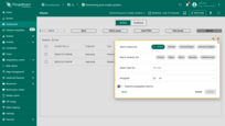
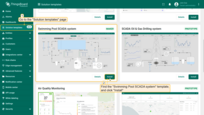
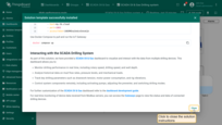
- Go to the “Solution templates” page. Find “Swimming Pool SCADA system” and click “Install” to start the installation process.
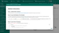
- Configuration instructions for this solution will be provided — follow the steps as instructed.
- Once done, click “Close” to complete the setup and proceed to the dashboard.
Dashboard
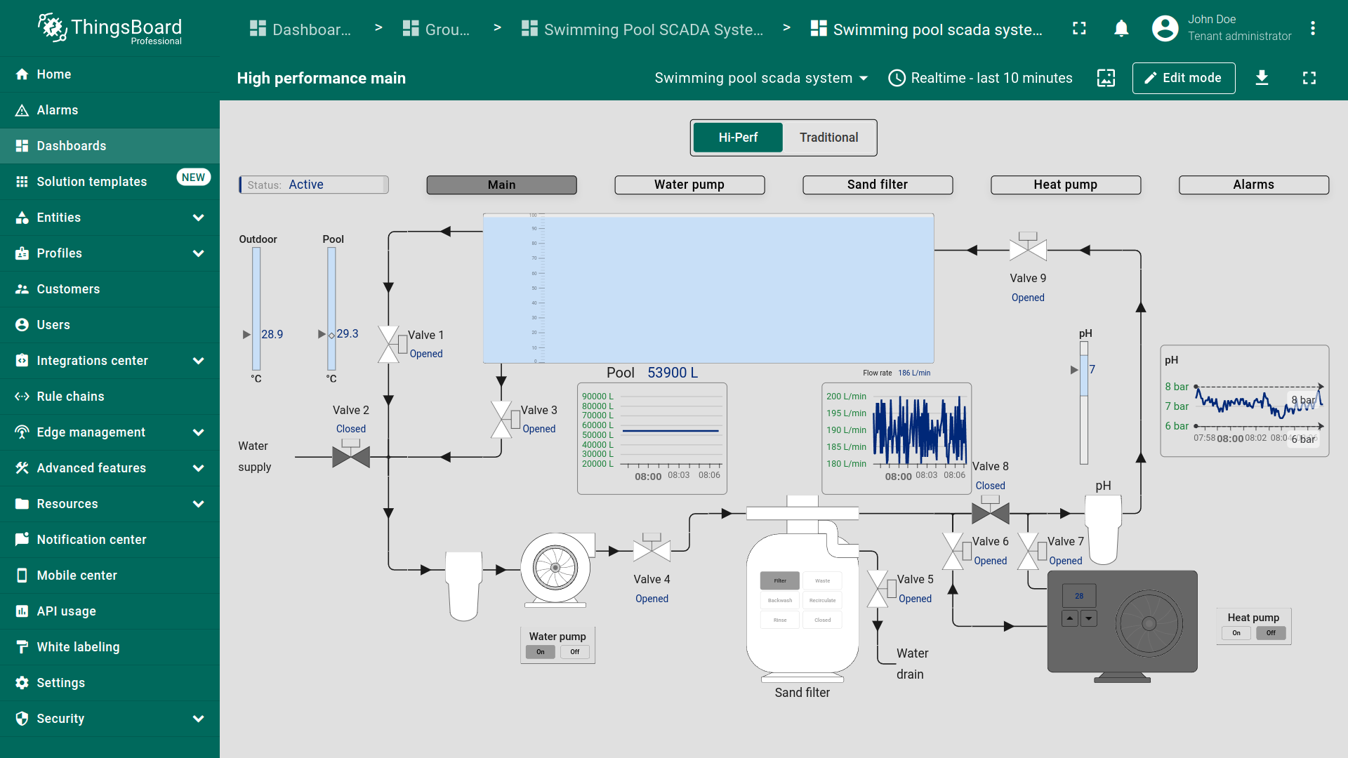
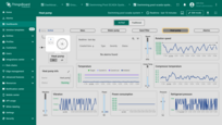
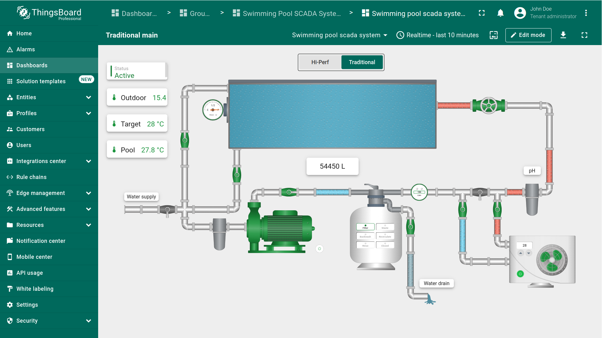
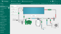
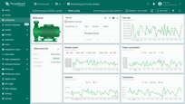
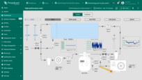
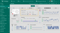
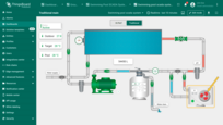
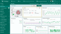
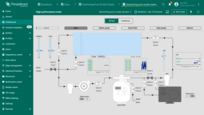
As part of this solution, we have developed a comprehensive Swimming Pool SCADA system dashboard that allows you to visualize, interact with, and control real-time data from multiple devices. The dashboard is designed to display critical information for water management, temperature control, and equipment performance. It allows operators to interact with various system components for real-time control and monitoring from any device.
Key features:
-
Interactive States: Easily navigate the system by clicking on individual devices to access detailed metrics of specific states, streamlining your workflow.
-
Flexible Layouts for Multi-Device Access: Whether you're using a desktop, tablet, or smartphone, the dashboard’s adaptive design ensures seamless operation and accessibility to your pool system anytime, anywhere.
-
Water Quality Management: Keep your pool in optimal condition by monitoring water levels and pH data. The system helps maintain balance and prevents water quality issues.
-
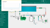
Temperature Control: Use outdoor temperature and pool temperature sensor data for intelligent heat pumps control. The system ensures that the water temperature is maintained efficiently according to predefined targets.
-
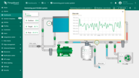
Equipment Monitoring: Monitor the performance of pumps, sand filters, and other critical equipment. The dashboard provides insights into rotation speed, vibration, flow rates, power consumption, and more to monitor operational efficiency.
-
Valve Control: Remotely control water flow across different segments of the system by controlling valves. This adds flexibility to the system and enables quick adjustments to water flow as needed. You can interact with the valves directly through the dashboard to turn them on or off as necessary.
-
Energy Management: Track energy usage for heat pumps, filtration systems, and other devices. Use this data to optimize energy efficiency and reduce costs.
-
Remote System Management: Take full control of your swimming pool system from anywhere. Operate pumps, switch between modes, and manage valves remotely.
SCADA systems are divided into two types:
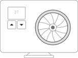
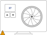
- High-Performance SCADA systems, which emphasize simplified interfaces, faster decision-making, and improved information perception efficiency.
- Traditional SCADA systems, which focus on basic monitoring and control.
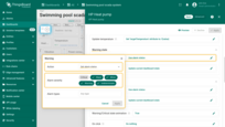
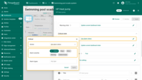
Choose the SCADA system type that suits you best:
For further customization of the Swimming Pool SCADA system dashboard refer to the dashboard development guide.
For real-time monitoring of device data received from Modbus servers, you can access the ThingsBoard IoT Gateways dashboard to view the status and data of connected devices.
System components
The SCADA Swimming Pool system includes:
- 14 operational devices, essential for monitoring and controlling various components of the pool system;
- An asset that gathers data from its connected devices and stores it as attributes for subsequent monitoring and control of various components within the SCADA system;
- The gateway transmits data from these devices to ThingsBoard, ensuring seamless device connectivity and data transfer within the SCADA system.
Devices
Choose the SCADA system type:
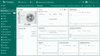
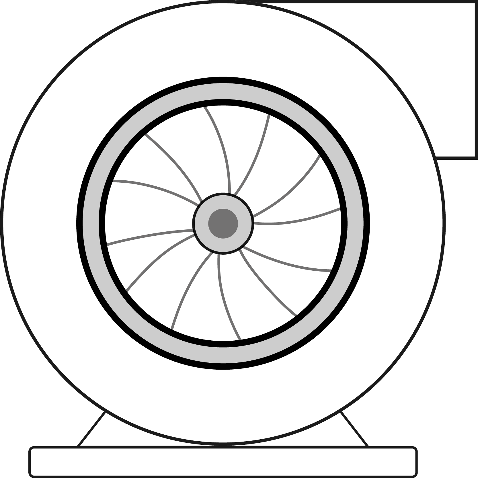
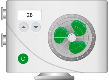
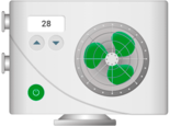
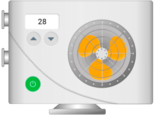
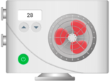
The system includes the 14 operational devices: Heat pump The heat pump controls the pool temperature and operates automatically based on predefined temperature settings. This behavior is managed within the Swimming Pool Device Rule Chain to ensure efficient energy usage and precise temperature regulation. Depending on the temperature readings, the heat pump will automatically:
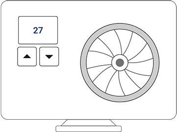
The following settings are available for the heat pump:
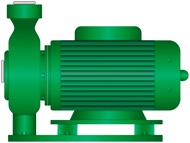
Water pump Manage the circulation of water throughout the pool by turning the pump on or off.
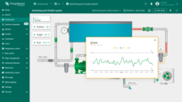
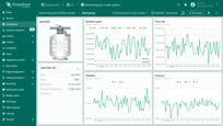
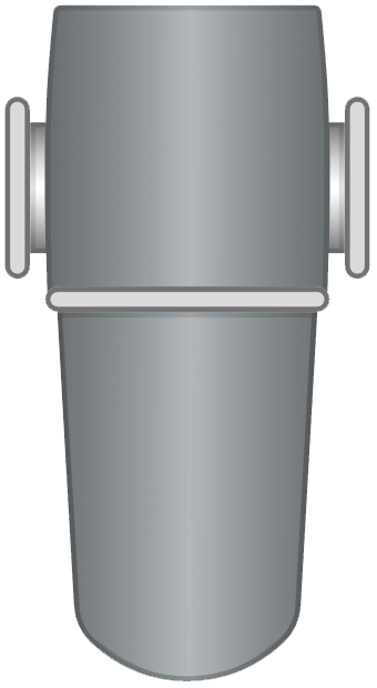
pH filter Ensure the water pH levels are within optimal ranges by managing the filtration and chemical treatment process. Pressing the pH filter will open the pH filter diagram in a popup window.
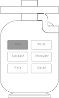
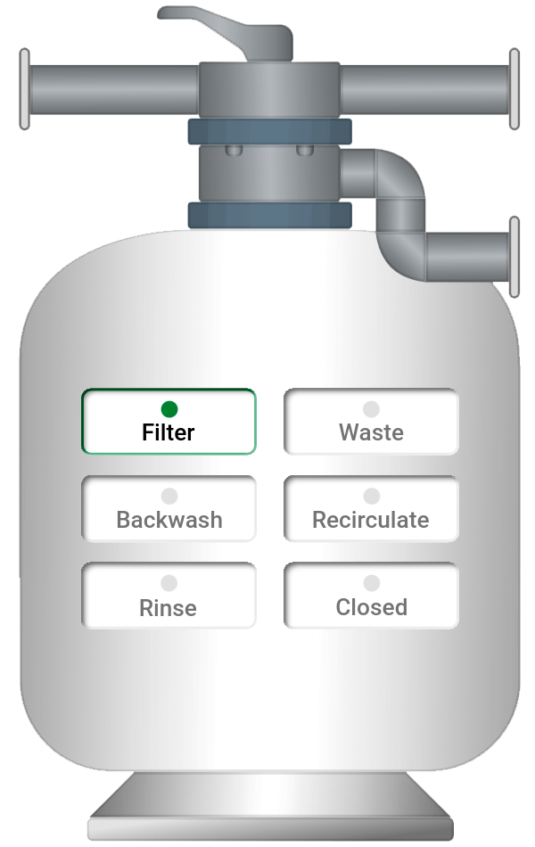
Sand filter Allow for efficient debris removal from the pool. The filter supports multiple functions, including filtration, wasting, backwashing, recirculation and rinsing, all of which can be controlled remotely via the SCADA system.
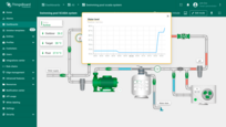
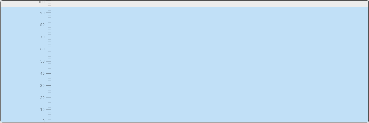
Water level meter Measure the water level in the pool, providing critical data to maintain optimal water levels and detect potential leaks.
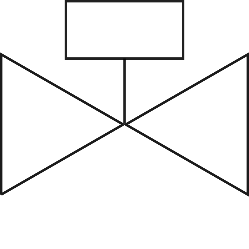
Valves Allow for precise control of water flow between different sections of the pool system. Pressing the valve will open or close it.
|
Asset
The Swimming Pool SCADA system includes a single asset named the SCADA Swimming Pool system. This asset serves as the central hub for collecting and processing data from all connected devices. The data collected by the asset is processed using Calculated fields and later used for monitoring and controlling various system components, including calculations that determine the status of each pipe—indicating whether water is flowing or not. The data is then visualized on the dashboard, allowing users to interact with and control devices while monitoring system performance in real time.
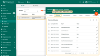
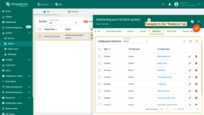
Gateway
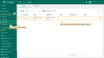
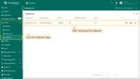
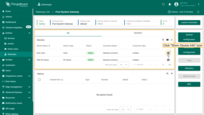
The ThingsBoard IoT Gateway integrates devices into the SCADA system in ThingsBoard, ensuring seamless connectivity and data transmission. The “Pool System Gateway” gateway configuration is accessible on the Gateways page in the Entities section.
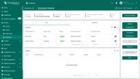
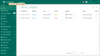
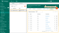
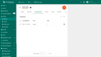
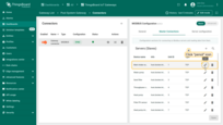
The Pool System Gateway displays connected devices and their status. Click “Show Device Info” icon next to the device to view detailed information, including its status and relevant metrics.
Connector configuration
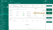
Let's go over the connector settings. Click the Connectors configuration button to display available connectors. Click on the Pool Connector to open its configuration settings. Navigate to the Master Connections tab, where you'll find connection parameters for connecting devices to the Modbus server and data processing settings for each device.
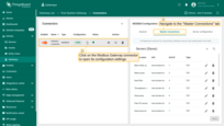
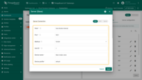
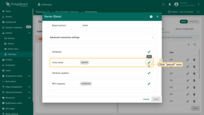
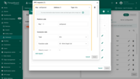
We’ll examine the configuration parameters using the “Main intake valve” device as an example. Click the pencil icon next to the device name to open its settings window.
In this template, we’re using an emulator to simulate devices and their telemetry data.
The host host.docker.internal and port 5021 are specific to your Modbus device. If you need to connect actual devices, replace the host and port values with the real ones.
A detailed description of other parameters, such as Method, Unit ID, and others, can be found on the Modbus Connector configuration page.
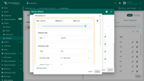
Scroll down to the “Time series” section. Here, you can configure the processing of incoming data. These settings will be interpreted in ThingsBoard as device telemetry data. To open the time series configuration, click the pencil icon. For more details on each parameter and setting in the “Time series” section, refer to the Modbus time series settings documentation.
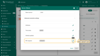
In the “RPC Requests” section, you can configure parameters for remote procedure calls (RPC) from ThingsBoard to the device. This section is necessary for sending commands and receiving responses from the device. For detailed information on each parameter in “RPC Requests”, refer to the Modbus RPC settings documentation.
Rule chain
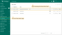
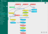
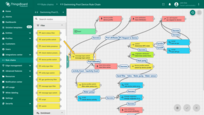
Each message passes through The Swimming Pool Device Rule Chain. Here, telemetry, attributes, and RPC requests are saved, alarms are generated, and control of the heat pump is performed.
Message processing flow:
- Alarm generation: Every message first passes through the device profile node. This step allows the system to generate alarms based on the conditions defined in the device profiles (such as for the heat pump, water pump, and sand filter). If the telemetry exceeds the set thresholds, alarms are triggered and displayed on the dashboard.
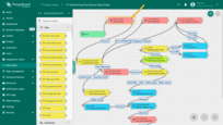
- Message type switch: After the initial profile processing, the message moves to the message type switch node. This node routes messages based on their type, such as telemetry data, attribute updates, or RPC requests. It sends each message down the appropriate path for further processing.
-
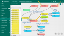
General logic – save attributes, time series, and RPC requests: Independent of the message type, these actions are performed for all devices.
- save attributes node: The telemetry data from devices is saved as attributes.
- save time series node: Time series data is saved for historical analysis and monitoring.
- rpc call request node: The system can generate and send RPC requests to devices. These RPC commands may turn devices on/off, change operational modes, or control valve positions. For example, valves can be opened/closed, and pumps can be activated/deactivated based on predefined conditions or manual requests.
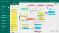
- Device profile filtering: Once the telemetry data is saved, the message is routed through the device profile switch node. This node filters the devices based on their profile, allowing for device-specific actions. When telemetry from the heat pump is detected, the system checks specific conditions—like target temperature, outdoor temperature, and pool temperature—through a switch node. If the telemetry conditions meet the thresholds for turning the heat pump on or off, an RPC request is sent to control the heat pump’s state.
Device profiles
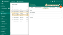
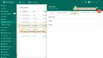
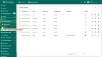
In ThingsBoard, a device profile is a set of configurations and rules that define the behavior of devices using it. Device profiles simplify managing devices with similar parameters. They include a rule chain for processing incoming messages and events, transport configuration, alarm rules, and other parameters. Learn more about the device profile here.
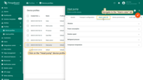
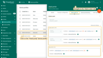
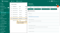
For the “Swimming Pool SCADA system” solution template, six device profiles were created to manage the 14 operational devices. These profiles set a “Swimming Pool Device Rule Chain” as the default rule chain to our devices, the transport configuration is set to default, and define specific alarm rules for them. Such as excessively high water temperature in the pool or exceeding the power consumption of the heat pump, etc.
Alarm rules
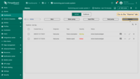
The Swimming Pool SCADA system includes alarm configurations for key devices, allowing operators to monitor critical conditions and respond swiftly to potential issues. Alarms are triggered based on predefined thresholds and rules defined in device profiles, helping to maintain the optimal performance of the system.
Device-Specific Alarms
Heat pump: The heat pump has five alarm rules based on the following metrics:
- Vibration levels
- Power consumption
- Rotation speed
- Refrigerant pressure
- Compressor temperature
Water pump: The water pump is monitored by four alarm rules based on:
- Vibration levels
- Power consumption
- Rotation speed
- Temperature
Sand filter: The sand filter is equipped with three alarm rules that track:
- Vibration levels
- Rotation speed
- Pressure
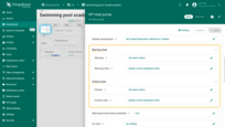
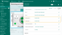
For example, let's take a closer look at the configuration of the “Rotation speed” alarm rule for the heat pump.
This rule has two severity levels:
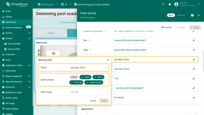
- If the value of the “rotationSpeed” key is greater than or equal to 0 and less than 50, and “running” equals 1, an alarm with a severity type of “Warning” will be triggered.
- If the value of the “rotationSpeed” key is greater than or equal to 200 and “running” equals 1, an alarm with a severity type of “Critical” will be triggered.
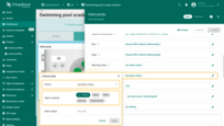
A separate rule is defined for clearing the alarm:
- If the value of the “rotationSpeed” key returns to the range of greater than or equal to 50 and less than 200, the alarm will be automatically cleared.
The configuration of other alarm rules is similar to the “Rotation speed” rule of the heat pump. Please review them for yourself.
For more about alarms and how to configure them, read here.
Conclusion
The Swimming Pool SCADA template provides a ready-to-use framework for managing swimming pool components. It ensures seamless integration between sensors, and ThingsBoard, allowing real-time data collection, processing, and visualization. This setup not only enhances operational efficiency but also provides a scalable and reliable solution for centralized supervision and control of swimming pool systems.
